20
HOW TO SET SLOPES (FALLS/GRADES)
Working Example 2 (when you do NOT know the grade to set)
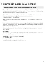
The following description explains the general principles of setting a Slope (Fall/Grade) using the
FRE-205, when you do NOT know the grade to set.
Equipment
You will need the FRE-205 laser level, its remote control, a surveying tripod, measuring staff (rod)
with mm scale and a laser detector/receiver.
Site Conditions
There are many diff erent work site scenarios. As an example, we are assuming that you are
outside, on a site with a clear fi eld of view and planning to set drainage falls.
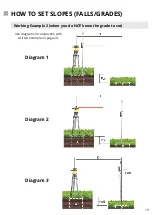
See Diagram 1
A
is a manhole cover with surveying tripod and attached FRE-205 laser level.
B
is a second manhole cover at a lower position, located the distance of “
D
” apart and by a fall of
“
F
”.
The planned sitework is to set a slope on the laser level to assist in digging a drainage channel to
join
A
to
B
.
Procedure
First measure distance “
D
”.
Next, attach the FRE-205 onto the surveying tripod, switch ON and allow it to auto level. The
tripod height is unimportant. Face keypad (in the Y axis) towards cover
B
.
Position your extended measuring staff on the ground next to the laser & clamp the detector to
pick-up the red rotating beam with a continuous tone on the detector.
Note & record the mm height from the measuring staff . (
See diagram 1
).
To determine & set fall F:
Before moving position from cover
A
, press the Manual Override button on the remote control
to disable the auto (self) levelling.
Do NOT un-clamp detector. Move position and place extended measuring staff over the
centre of cover
B
, holding it vertically. (
See diagram 2
). Un-clamp detector and move it up the
measuring staff to pick-up the laser beam with a continuous tone. (
See diagram 3
). Record the
new height value. The site Fall “
F
” is this value minus the value taken previously at cover
A
.
Return the detector down to the lower position again & clamp tight. (See diagram 2).

