background image

ENGLISH


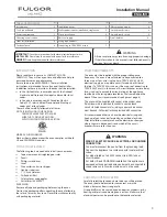
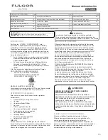
INSTALLATION  NOTES 

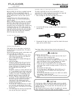
1.  Do not slide oven across floor. Damage to floor covering 

or floor could result. 

2.  The oven support surface must be a minimum 3/4" (2cm) 

thick plywood platform.  

For single ovens, it must support 202 pounds.  

The platform must be solid, level and flush with the bottom of 

the cabinet cut out. 

3.  Use extreme caution when moving or installing the oven.  

It is very heavy.  

DO NOT LIFT THE OVEN BY THE DOOR HANDLE, 

remove the door for easier handling and installing.  

See REMOVING THE DOOR in the maintenance section 

of the Operating Instructions. 

4.  Be very careful when moving or installing the oven to  

avoid damage to the oven frame or damage to the cabinets. 

5.  Be sure to level the oven. An oven that is not level may 

provide poor or inconsistent baking results. 

6.  Be careful when placing oven. DO NOT pinch the conduit 

between the oven back. 


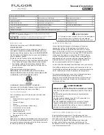
 WARNING 

Before installing or removing, turn power OFF at the service 

panel. Lock service panel to prevent power from being turned 

ON accidentally. 

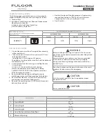
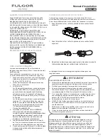
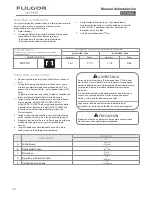
Securely fasten oven to cabinet  using the screws provided. 

Failure to do so could result in oven moving or tipping 

during use and causing damage to the oven or cabinets or 

personal injury. 


Know how to disconnect the power to the oven at the circuit 

breaker or fuse box in case of an emergency. 


 CAUTION 

Unit is heavy and requires at least two people or proper 

equipment to move. 


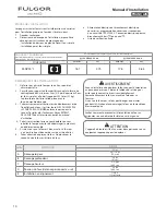
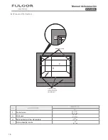
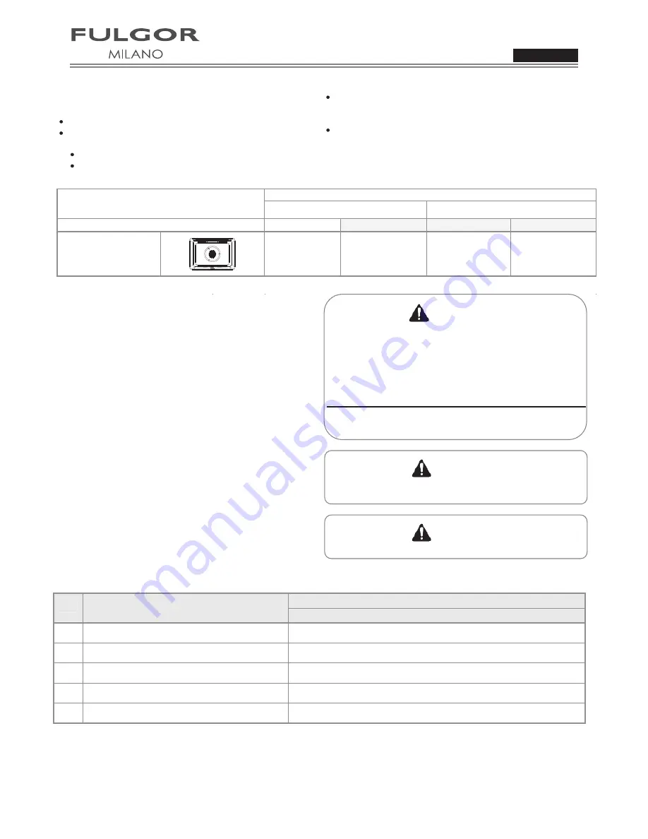
Ltr. 

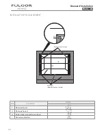
DIMENSION 

Cutout Width 

Cutout Depth 

Cutout Height 

Minimum Spacing 

Electrical Ratings and Maximum Connected Load 

TECHNICAL DATA   

For cutout dimensions see following section titled:  

Preparing location 


SINGLE OVEN 

Amperes 

kW 

Amperes 

kW 

@ 120V/240V  60Hz

@ 120V/208V  60Hz

SINGLE 

30” 

28 7/16” 

(72,2 cm) 

24” 

(61 cm) 

27 3/8” 

(69,5 cm) 

34” 

(86,5 cm) 

1/2” 

(1,3 cm) min 

Oven Position (distance from floor)

STEPS FOR INSTALLATION 

The following pages provide the necessary information for 

proper installation of the oven and are arranged as follows: 

Technical Data 
Installation Cutout Dimensions, Required Clearances and 

Mounting instructions for: 

-  Under counter Installation, Single Oven 

-  Wall Installation, Single Oven 

Electrical Supply and Wiring Requirements, Programming 

required if connecting to 

120V/

208V Circuit. Electrical 

Connections for 3-wire or 4-wire Branch Circuit. 
Final Checklist 


 CAUTION 


Do not remodel the oven.

ENGLISH


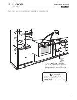
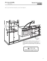
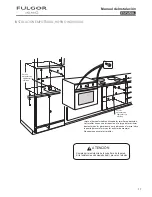
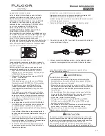
WALL OR UNDER COUNTER INSTALLATION, SINGLE OVEN 


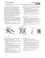
Confirm the strength of the wall surface.

When the strength of the wall surface is weak,

give reinforcement.

CAUTION

F4SP30*1

16.1

3.79

17.8

3.64

4

ENGLISH

Installation Manual

Summary of Contents for MILANO

Page 1: ...w Installation Instructions Instructions d Installation Instrucciones de Installación F4SP30 1 ...

Page 2: ......

Page 3: ... is manufactured to be connected to a three wire or four wire single phase 120V 240V 60 Hz AC electrical supply on a separate circuit fused on both sides of the line If a 120V 208V circuit must be used see Connecting to 120V 208V Circuit in this manual A circuit breaker or time delay fuse sized not to exceed the circuit rating of the appliance specified on the rating plate located on the frame beh...

Page 4: ... do so could result in oven moving or tipping during use and causing damage to the oven or cabinets or personal injury Know how to disconnect the power to the oven at the circuit breaker or fuse box in case of an emergency CAUTION Unit is heavy and requires at least two people or proper equipment to move Ltr DIMENSION A Cutout Width B Cutout Depth C Cutout Height D E Minimum Spacing Electrical Rat...

Page 5: ...s weak give reinforcement CAUTION Electrical supply junction box Secure oven to cabinet using the screws provided Screws should be inserted through the mounting holes in the positions indicated in the frame open door to see frame and mounting holes Do not over tighten screws Electrical supply junction box 5 ENGLISH Installation Manual ...

Page 6: ...tr DIMENSION F Cutout Width G Cutout Height H Visible part of the mounting strips SINGLE 30 30 1 16 76 4 cm 28 1 32 71 2 cm 3 4 1 9 cm Mounting strip Finished sides the cabinet 61 cm I Cutout Depth 24 6 ENGLISH Installation Manual ...

Page 7: ... oven If cold water pipe is interrupted by plastic non metallic gaskets union connections or other insulating materials DO NOT use for grounding DO NOT ground to a gas pipe DO NOT have a fuse in the NEUTRAL or GROUNDING circuit A fuse in the NEUTRAL or GROUNDING circuit could result in an electrical shock Check with a qualified electrician if you are in doubt as to whether the appliance is properl...

Page 8: ... Set the clock by following these steps Clock is now set 5 Test the bake mode by following this step Move cooking mode knob to BAKE position Move the knob back to OFF position to stop cooking 6 To check the other oven functions refer to the Using the Oven Controls section of the USER MANUAL 7 If the oven is working properly turn off the power supply to the oven 8 Place the cover on the junction bo...

Page 9: ...ants d air peuvent être provoqués par des portes ouvertes ou des fenêtres ou par des ventilateurs ou l air conditionné Assurez vous que le branchement peut arriver jusqu à l emplacement choisi Le four ne doit être branché qu avec des fils de cuivre ou aluminium Si un câble en aluminium est fourni pour la connection du four au circuit électrique il est nécessaire utiliser les connecteurs énumérés p...

Page 10: ...ger ou basculer pendant l utilisation et endommager le four ou le meuble ou blesser quelqu un Sachez comment déconnecter l alimentation du four au disjoncteur ou au boîtier de fusibles en cas d urgence ATTENTION L appareil est lourd et il faut au moins deux personnes ou un équipement approprié pour le déplacer DIMENSION A Découpe largeur B Découpe profondeur C Découpe hauteur D E Installation en a...

Page 11: ...our au meuble en utilisant les vis fournis Les vis doivent être insérées dans les trous de montage dans les positions indiquées das le montantes ouverez la porte pour voir le montant et les trours de montage Ne serrez pas trop les vis Boite de raccordement d alimentation eléctrique Boite de raccordement d alimentation eléctrique 11 FRANÇAIS Manuel d Installation ...

Page 12: ...e largeur G Découpe hauteur H Partie visible des bandes de support SIMPLE 30 3 4 po 1 9 cm 30 1 16 po 76 4 cm 28 1 32 7 2 cm po 1 Baguettes de montage Lettre po 61 cm I Découpe profondeur 24 po même finition que l arrière 12 FRANÇAIS Manuel d Installation ...

Page 13: ... des joints non métalliques des connexions d union ou d autres matériaux isolants NE L UTILISEZ pas pour mettre à la masse pas la masse à un tuyau à gaz N AYEZ PAS de fusible en position neutre ou un circuit à la masse Un fusible dans un circuit neutre ou à la masse pourrait entraîner une électrocution Vérifiez avec un électricien qualifié si vous avez un doute si votre appareil est correctement r...

Page 14: ...s le MANUEL D UTILISATION 7 Si le four fonctionne correctement éteignez l alimentation du four 8 Placez le couvercle sur le boîtier de raccordement et vérifiez que le couvercle est bien attaché et allumez le four ces instructions d INSTALLATION le é maisons mobiles et les véhicules de parc ou dans les régions L horloge est maintenant réglée ff ainsi que Remettez manuel d UTILISATION au propriétair...

Page 15: ...unca que los niños jueguen con el material de embalaje REQUISITOS DE CORRIENTE El horno ha de estar abastecido con el voltaje y la frecuencia apropiados El horno ha sido fabricado para conectarse a una alimentación eléctrica de una sola fase de 3 cables o 4 cables 120V 240V 60 Hz AC en un circuito separado con fusible en ambos lados de la línea Si se tiene que usar un circuito 120V 120V 208V de es...

Page 16: ...e provocar que el horno se mueva o se vuelque durante el uso y provoque daños al horno y a los muebles o heridas personales Sepa como se desconecta la corriente del horno del cortocircuito y de la caja de fusibles en caso de emergencia PRECAUCIÓN El aparato es pesado y para moverlo requiere como mínimo dos personas o el equipamiento apropiado Letra DIMENSIONES A Ancho hueco B Profundidad hueco C A...

Page 17: ...o al mueble utilizando los tornillos en dotación Los tornillos tienen que introducirse a lo largo de los orificios de montaje en las posiciones que se indican en el marco abra la puerta para ver el marco y les orificios de montaje No apriete en exceso los tornillos Caja de empalme de alimentación eléctrica Caja de empalme de alimentación eléctrica 17 ESPAÑOL Manual de Instalación ...

Page 18: ... Ancho hueco G Alto hueco H Parte visible de la tiras de montaje Mounting strip Finished sides the cabinet INDIVIDUAL 30 3 4 1 9 cm 30 1 16 76 4 cm 28 1 32 71 2 cm ESPAÑOL 61 cm I 24 Profundidad de recorte 18 ESPAÑOL Manual de Instalación ...

Page 19: ...erra al horno Si la línea de agua fría se interrumpe con empaques de plástico no con juntas de estanquidad metálicas conexiones de unión o materiales aislantes NO utilice para la puesta a tierra NO conecte a tierra a la tubería del gas NO tenga un fusible en el circuito de NEUTRO o de TIERRA Un fusible en el circuito de NEUTRO o en el de TIERRA puede provocar descargas eléctricas Consulte con un e...

Page 20: ...siguientespasos Mueva la perilla del modo de cocción en la posición de BAKE Gire la perilla hacia la posición de OFF para parar la cocción 6 Para controlar las demás funciones del horno tome como referencia la sección Uso de los controles del horno To del MANUAL DE USO Y MANTENIMIENTO 7 Si el horno trabaja de manera apropiada apague la corriente del horno 8 Coloque la tapa sobre la caja de empalme...

Page 21: ...Notes 21 ...

Page 22: ...Notes 09FL5960 12 14 22 ...

Page 23: ......

Page 24: ...09FL5960 12 14 ...

Reviews: