5/14/2018
Fuling Inverter User Manual - slidepdf.com
http://slidepdf.com/reader/full/fuling-inverter-user-manual
36/54
Function
Code
Name
Setting Range
Default
Value
F4.29
Multi-Speed 0
- 100. 0 100. 0%
~
0.0%
F4.30
Multi-Speed 1
- 100. 0 100. 0%
~
0.0%
F4.31
Multi-Speed 2
- 100. 0 100. 0%
~
0.0%
F4.32
Multi-Speed 3
- 100. 0 100. 0%
~
0.0%
F4.33
Multi-Speed 4
- 100. 0 100. 0%
~
0.0%
F4.34
Multi-Speed 5
- 100. 0 100. 0%
~
0.0%
F4.35
Multi-Speed 6
- 100. 0 100. 0%
~
0.0%
F4.36
Multi-Speed 7
- 100. 0 100. 0%
~
0.0%
Note: The multi-speed symbol defi nes the operation direction. If it is nega tive, the operation direction
is reverse. Frequency setting 100.0% is corresponding to maximum frequency(F0.04).
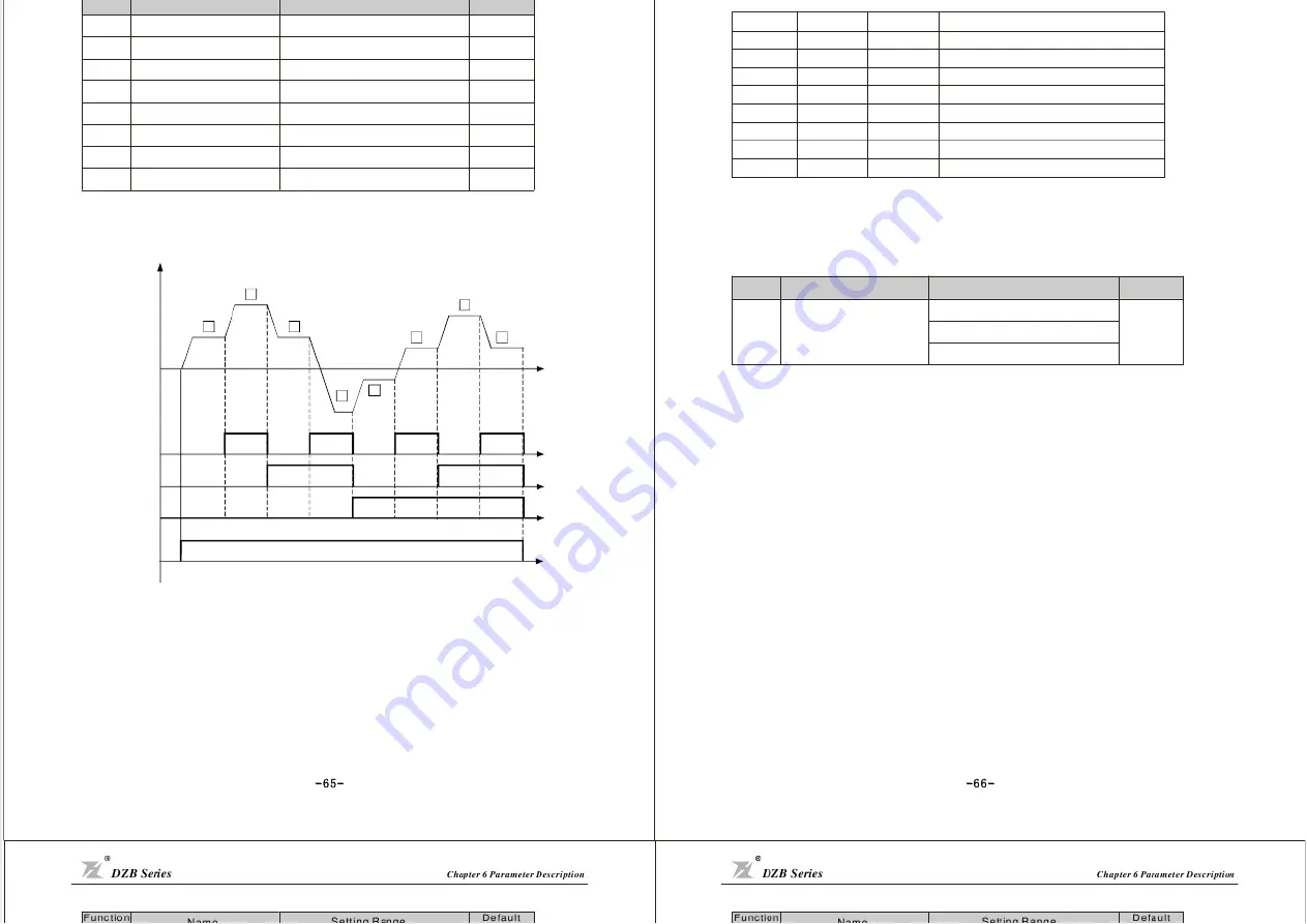
Fig.6-20 multi-speed logic Diagram
p
p
、
、
0: no protection. There is no motor overloading prot ection characteristic (caution to use), and thereby the
inverter has no protection to the overl oaded motor.
1: normal motor (with low speed compensation). As general motor has a poor heat emission at low speed,
the relevant electronic thermal protection should be regulated properly.The low speed compensation
characteristic here mentione d is to switch down the overloading protection threshol d for the motor with
an operation frequency lower than 30 Hz.
2: Variable frequency motor (without low speed compensation). As the heat emission of special variable
frequency motor is not affected by speed, it is not re quired to regulate the protection value for low speed
operation.
- 6 5 -
- 6 6 -
F5 Protection Parameters
S1
OFF
ON
OFF
ON
OFF
ON
OFF
ON
S2
O F F
O F F
ON
ON
O F F
O F F
ON
ON
S 3
O F F
O F F
O F F
O F F
O N
O N
O N
O N
Multi-Speed 0
Multi-Speed 1
Multi-Speed 2
Multi-Speed 3
Multi-Speed 4
Multi-Speed 5
Multi-Speed 6
Multi-Speed 7
Current segment of multi-speed control
F5.00
Motor Overload
Protection Option
0 No pr otec ti on
:
1 normal mot or
:
2 Variable Frequency motor
:
1
Function
Code
Name
Setting Range
Default
Value
ON
ON
ON
ON
ON
ON
ON
1
2
3
4
5
6
7
0
S1
S2
S3
t
t
t
t
ON
t
Output
frequency
Operation
command


