5/14/2018
Fuling Inverter User Manual - slidepdf.com
http://slidepdf.com/reader/full/fuling-inverter-user-manual
7/54
Chapter 3 Mechanical and Electrical Installation
3. 1
Mechanical Installation
1) Ambient temperature: Ambient temperature influences the inverter life greatly, so it should be within
the range of -10 ~50 .
2) Mount the inverter in a flame retardant s urface and the clearance around the inverter shall be enough
because the inverter will generate lots of heat during runni ng, besides mount the inverter on the base
vertically with screws.
3) Mount in the location where vibration is le ss than 0.6G; the inverter shall be far away from impact ing
lathe.
4) Please do not install the inverter in the place with direct sunlight, high humidit y and water.
5) Mount the inverter in the location free o f corrosive gas, explosive gas or combustible gas.
6) Mount the inverter in the location free of oi l dirt, dust, and metal powder.
1. Installation Environment
2.Installation Location
℃
℃
D Z B
up
right
A
≥
1 0 0 m m
≥
1 0 0 m m
A
D Z B
D Z B
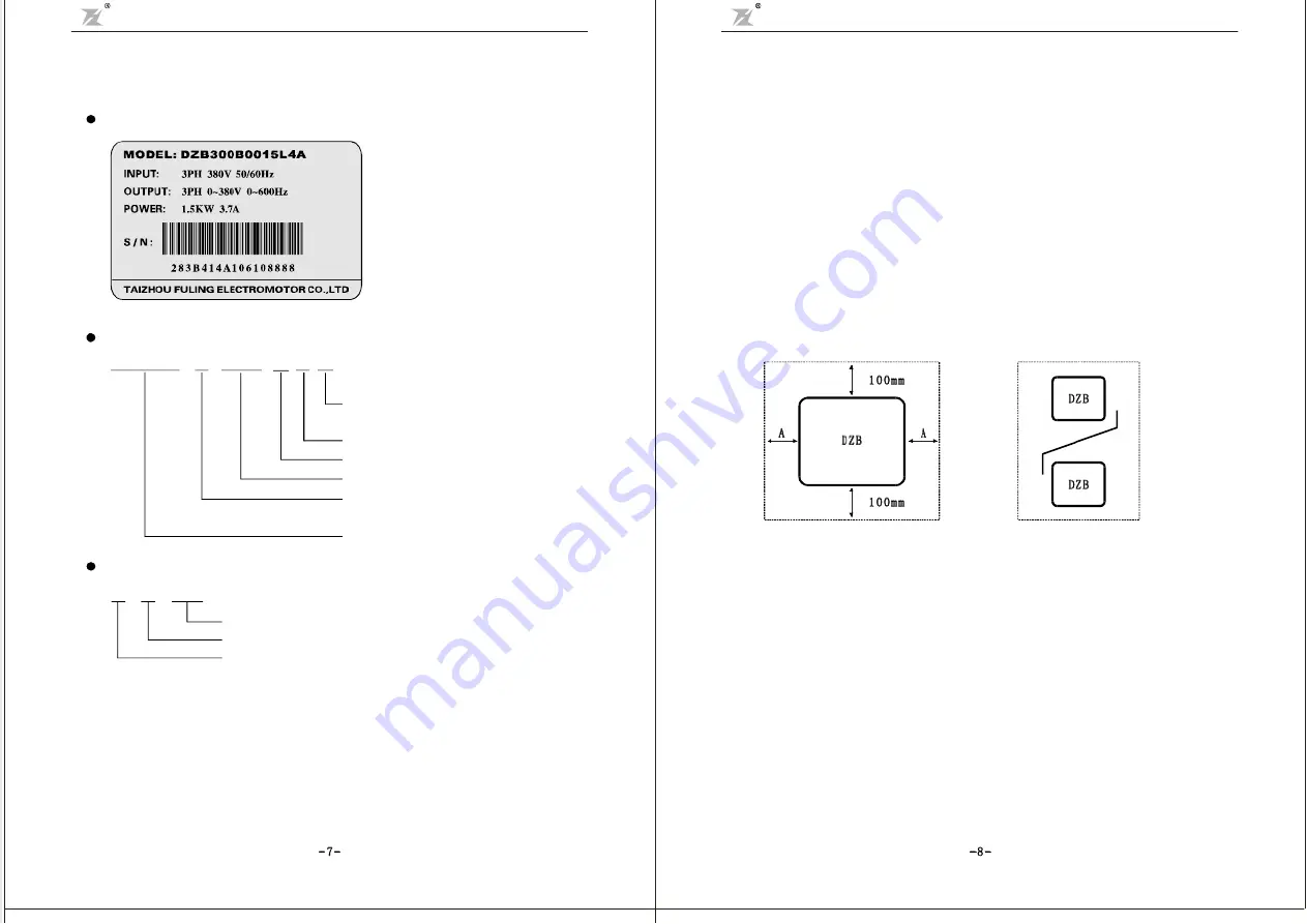
Note: No need to consider the dimension
A for inverter of 22kW or below.
A shall be bigger than 50mm for the
inverter of 22kW or above
Note: Install an airflow- guidance
plate for the up and down installation
of inverters.
Fig.3-1 DZB Series Inverter Installation Location
The user shall focus on the heat dissipation issues when installing the inverter, and pay attention to the
following points:
1) Install the inverter vertically so th at the heat may be expelled from the top, but do not install the
inverter upside down. When two Variable Speed Drives are mou nted up and dow n, an air flow
diverting plate should be fixed in between as shown in Fig. 3-1.
2) Installation space is shown in Fig.3-1 so as to ensur e the heat dissipation space, but consider the
heat dissipation of other components when placing the i nverter.
3) The installation bracket must be flame retardant.
4) Install the heat sink outside of the cabinet if the i nverter is installed in the area with metal powder.
And in this case, the space inside the sealing cabi net shall be big enough.
Nameplate
D Z B 3 0 0
B
0 0 1 5
L
4 A
Function level code: A -braking unit inside
B -non braking unit
Input voltage
Freq. Range
Applicable motor capacity
Series
General-Purpose Model
Fan&Pump Model
Seri es name
Serie s
2-220V 4-400V 6-660V
L 0-600.0Hz
0 01 5 1 . 5K W
B:
P:
: DZB300
:
: :
:
为
:
Description ofACMotor Drive Model:
Production number
Production month
Production year
8 8 8 8
1 0
0 6
Description of Serial Number::
2.2 Nameplate Information
- 7 -
- 8 -
I ns ta ll at ion o f s i ng le i nv er te r
U p a nd d ow n i nst al la ti on o f i nv er te rs
Chapter 2 Product Introduction
DZB Series
Chapter 3 Mechanical and Electrical Installation
DZB Series


