background image

13

WARNING!

 This air compressor must be used with a residual current device with a 

rated residual current of 30mA or less.

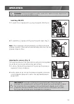
Switching ON/OFF.

1

. To switch the compressor On, pull up the switch (10) (Fig. 6).

2.

 To switch the compressor Off, press the switch down (Fig. 7).

Note:

 The compressor will automatically cut off when the tank 

pressure reaches 10 bar and will automatically start when the tank 

pressure drops to 8 bar.

Adjusting the pressure (Fig. 8)

The output pressure of the quick-lock coupling can be regulated 

to suit the air tool connected and the task at hand.

1.  

To do so, first back the pressure off by turning the pressure 

regulator (14) anti-clockwise.

2. 

 Set the pressure by turning the pressure regulator clockwise 

until the desired pressure is met on the regulated pressure 

gauge (left).

OPERATION

IMPORTANT!

 The motor is fitted with an overload switch. If the compressor 

overloads, the overload switch switches off the equipment automatically to protect 

the compressor from overheating. If the overload switch triggers, switch off the 

compressor using the ON/OFF switch and wait until the compressor cools down. 

Then press the overload switch and restart the compressor.

psi
bar

2

4

6

8

10

150

200

100

50

1

psi

50

150

200

100

4

6

8

10

12

bar

Fig. 6

Fig. 7

Fig. 8

10

10

14

Summary of Contents for FBACVT-5030

Page 1: ...GES 2 AIR OUTLETS INSTRUCTION MANUAL WARNING Read all safety warnings and all instructions Failure to follow the warnings and instructions may result in electric shock fire and or serious injury Save...

Page 2: ...livery FAD 164 l min Tank Volume 50 l Max Working Pressure 10 bar 145 psi Oil SAE 15W 40 IP Rating IP20 Weight 46 kg Free Air Delivery The free air delivery value was measured in accordance with Claus...

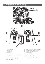
Page 3: ...eather oil filler opening 10 ON OFF Switch 11 Oil Drainage Screw Oil level window 12 Regulated Output Pressure Gauge 13 Quick lock Coupling regulated compressed air 14 Pressure Regulator 15 Tank Press...

Page 4: ...OUR PRODUCT Page 02 INTRODUCTION Page 05 SAFETY INSTRUCTIONS Page 05 ASSEMBLY Page 10 OPERATION Page 13 MAINTENANCE Page 15 TROUBLE SHOOTING Page 17 DESCRIPTION OF SYMBOLS Page 18 CONTENTS Page 18 WAR...

Page 5: ...or has been designed for 230V and 240V only Always check that the power supply corresponds to the voltage on the rating plate Note The supply of 230V and 240V on Full Boar tools are interchangeable fo...

Page 6: ...tions Water entering a power tool will increase the risk of electric shock d Do not abuse the cord Never use the cord for carrying pulling or unplugging the power tool Keep cord away from heat oil sha...

Page 7: ...from the power source and or the battery pack from the power tool before making any adjustments changing accessories or storing power tools Such preventive safety measures reduce the risk of starting...

Page 8: ...ressurised air to bleed from the tank from the safety valve and then remove the electrical plug from the power supply Check the maximum pressure rating of any tools or accessories that you intend usin...

Page 9: ...ssor directly on to any part of a persons body Do not attempt to block the air outlet with your finger or any part of your body The tool must be used only for its prescribed purpose Any use other than...

Page 10: ...air is dry and dust free Do not set up the compressor in damp or wet areas The compressor may only be used in suitable areas with good ventilation and an ambient temperature from 5 C to 40 C There mus...

Page 11: ...Place the support foot bolt up through the hole in the supporting bracket 2 Secure the support foot in place with the nut 3 Repeat steps 1 and 2 to fit the second foot Replacing the air breather 9 Fi...

Page 12: ...Secure the assembly by tightening the screw into the top of the filter Installation of the intake air filter 2 Fig 5 1 Remove the shipping plug with a screwdriver or similar 2 Screw the assembled int...

Page 13: ...cted and the task at hand 1 To do so first back the pressure off by turning the pressure regulator 14 anti clockwise 2 Set the pressure by turning the pressure regulator clockwise until the desired pr...

Page 14: ...ssure 10 bar is reached Fig 9 2 Hold the ring on the safety relief valve and pull it outwards Air should discharge from the valve Fig 10 3 When the ring on the safety relief valve is released the air...

Page 15: ...ief valve or remove its seal Check the oil level at regular intervals Place the compressor on a level and straight surface The oil level must be between the two marks MAX and MIN on the oil level wind...

Page 16: ...ast every 300 hours in service A clogged intake filter will decrease the compressors performance dramatically 1 Remove the air intake filter from the compressor and undo the screw on the top of the ai...

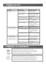
Page 17: ...ed by a service centre The drainage valve leaks Ensure it is shut off properly The compressor starts pressure is shown on the pressure gauge but no pressure to the air tool Loose hose connections Chec...

Page 18: ...Emissions Conformity EMC Ingress protection from water lP20 Warning The equipment is remote controlled and may start up without warning Distributed by Ozito Industries Pty Ltd AUSTRALIA Head Office 1...

Page 19: ......

Page 20: ...ilable to you under law The warranty covers manufacturer defects in materials workmanship and finish under normal use 1 YEAR WARRANTY Your product is guaranteed for a period of 12 months from the orig...

Reviews: