background image

15

Unregulated quick lock coupling

Air tools can also be attached to the unregulated quick lock 

coupling (14) (Fig. 26), but the output pressure level may 

fluctuate. 

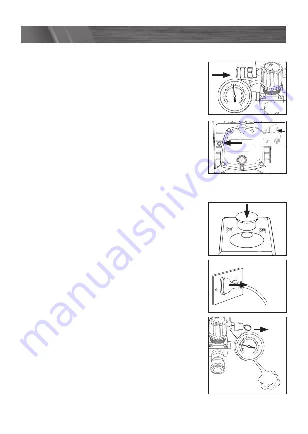
Overload switch

The motor is fitted with an overload switch (17). If the 

compressor overloads, the overload switch turns off the 

equipment automatically to protect the compressor. If the 

overload switch triggers, switch off the compressor using the 

ON/OFF switch (9) and wait until the compressor cools down. 

Then press the overload switch (17) and restart the compressor 

(Fig. 27). 

Note.

 Long supply cables, extensions, cable reels etc. cause a drop in voltage and can 

impede motor start-up. 

Turning off

1.    After the task has been completed, switch off the 

compressor by pressing down the on/off switch (9) (Fig. 28). 

2.    Wait for the pressurised air to bleed from the release valve 

under the pressure switch cover.

3    Switch off the power supply and remove the electrical  

plug (Fig. 29).

4.   Pull the ring on the safety valve (11) outwards, releasing 

the remaining compressed air in the tank. Release the ring 

so that the safety valve closes (Fig. 30).

Psi

Bar

10

8

6

4

2

0

50

100

150

200

12

14

Psi

Bar

10

8

6

4

2

0

50

100

150

200

12

14

OPERATION

Psi

Bar

10

8

6

4

2

0

50

100

150

200

12

14

Psi

Bar

10

8

6

4

2

0

50

100

150

200

12

14

Psi

Bar

10

8

6

4

2

0

50

100

150

200

12

14

Psi

Bar

10

8

6

4

2

0

50

100

150

200

12

14

Fig. 26

Fig. 27

Fig. 28

Fig. 29

Fig. 30

Summary of Contents for FBT-5100U

Page 1: ...ilure to follow the warnings and instructions may result in electric shock fire and or serious injury Save these instructions for future reference 0916 AIR COMPRESSOR ORIGINAL INSTRUCTIONS 2 5HP 50L T...

Page 2: ...S MODEL NO FBT 5100U KNOW YOUR PRODUCT 1 Intake air filter 2 Pressure tank 3 Wheel 4 Supporting foot 5 Quick lock coupling regulated compressed air 6 Locking collar 7 Pressure gauge for reading the re...

Page 3: ...Psi Bar 10 8 6 4 2 0 50 100 150 200 12 14 Psi Bar 10 8 6 4 2 0 50 100 150 200 12 14 20 21 3 KNOW YOUR PRODUCT cont 1 2 3 8 14 15 22 23 24 16 17 18 9 19 10 11 4 12 5 7 13 6...

Page 4: ...PRODUCT Page 02 INTRODUCTION Page 05 SAFETY INSTRUCTIONS Page 05 PRE SETUP CHECKS Page 10 ASSEMBLY Page 10 PREPARATION Page 13 OPERATION Page 14 TROUBLESHOOTING Page 16 MAINTENANCE Page 17 DESCRIPTION...

Page 5: ...th this tool for future reference Before you connect the equipment to the mains supply make sure that the data on the rating plate are identical to the mains data To reduce the risk of electric shock...

Page 6: ...entering a power tool will increase the risk of electric shock d Do not abuse the cord Never use the cord for carrying pulling or unplugging the power tool Keep cord away from heat oil sharp edges or...

Page 7: ...aking any adjustments changing accessories or storing power tools Such preventive safety measures reduce the risk of starting the power tool accidentally d Store idle power tools out of the reach of c...

Page 8: ...air tank of the compressor this could dangerously weaken the tank and will void the warranty Do not use the compressor outdoors when it is raining or on a wet surface either situation could cause an...

Page 9: ...o prevent power loss and possible damage to the motor After long working periods external metal parts could be hot After using the compressor switch off the on off button disconnect the power supply a...

Page 10: ...intake air is dry and dust free The compressor may only be used in suitable rooms with good ventilation and an ambient temperature from 5 C to 40 C There must be no dust acids vapours explosive gases...

Page 11: ...econd wheel Fitting the supporting feet 1 Insert one of the supporting foot bolts 24 up through a supporting foot 4 Fig 7 2 Place a flat washer onto the supporting foot bolt 24 Fig 8 3 Insert the supp...

Page 12: ...ey supplied 22 tighten the 2 grub screws on both transport handle fixtures 20 Fig 14 Replacing the oil sealing plug 1 Remove the transportation cover from the oil filler opening with a screwdriver Fig...

Page 13: ...after 100 hours of operation Thereafter the oil should be drained and refilled after every 500 hours in service 1 Unscrew and remove the oil sealing plug 15 Fig 19 2 Fill the crank case until the oil...

Page 14: ...low adjustment 3 You can adjust the level of output pressure by turning the pressure regulating knob 8 To increase the air pressure rotate the regulating knob clockwise To decrease the pressure rotate...

Page 15: ...s cable reels etc cause a drop in voltage and can impede motor start up Turning off 1 After the task has been completed switch off the compressor by pressing down the on off switch 9 Fig 28 2 Wait for...

Page 16: ...ts but there is no pressure in the tank 1 Leak in the non return valve 1 Replace the non return valve 2 The seals are damaged 2 Check the seals and have any damaged seals replaced by a service centre...

Page 17: ...33 WARNING Take care when discharging air through the safety valve drainage screw or the air outlet The discharged air can cause dust stones or any other foreign particles to be blown through the air...

Page 18: ...h day by opening the drainage screw 12 at the bottom of the tank The drainage screw can be opened by turning it in an anti clockwise direction Fig 34 Be sure to re tighten the drainage screw before th...

Page 19: ...he compressor slightly 4 When the oil has drained out re fit the oil drainage screw 16 5 Remove the oil sealing plug 15 and pour the new oil through the oil filler opening until it reaches the mid poi...

Page 20: ...er minute no No load speed Warning Wear eye protection Wear hearing protection Read instruction manual Beware of electrical voltage Beware of hot parts Before using for the first time check the oil le...

Page 21: ...ashers for fitting feet 2 x Nuts for fitting the feet 2 x Axle Bolts 2 x Spring Washers 4 x Washers for fitting the wheels 2 x Nuts for fitting the axles 1 x Instruction Manual Bunnings 489 499 Avebur...

Page 22: ...the device to abnormal environmental conditions or by lack of care and maintenance Damage to the device caused by abuse or incorrect use for example overloading the device or the use or unapproved too...

Reviews: