background image

M

M

D

D

2

2

2

2

7

7

8

8


H

H

i

i

g

g

h

h


P

P

e

e

r

r

f

f

o

o

r

r

m

m

a

a

n

n

c

c

e

e


M

M

i

i

c

c

r

r

o

o

s

s

t

t

e

e

p

p

p

p

i

i

n

n

g

g


D

D

r

r

i

i

v

v

e

e

r

r


V

V

1

1

.

.

0

0


                                                      8 


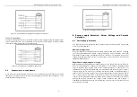
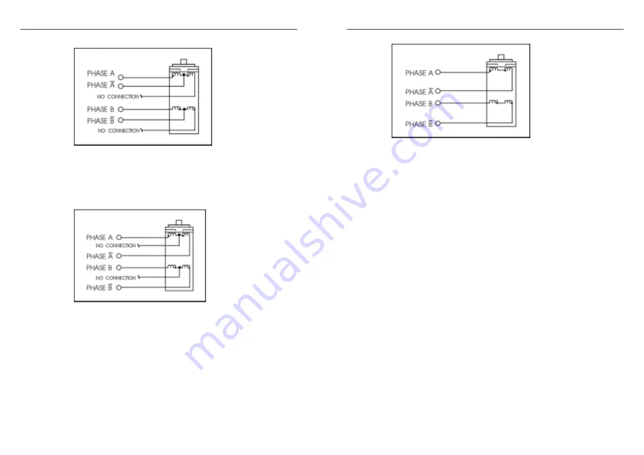
Figure 6: 6 Lead Half Coil (Higher Speed) Motor Connections 


Full Coil Confuguration 

The full coil configuration on a six lead motor should be used in applications where higher torque 
at lower speeds is desired. This configuration is also referred to as full copper. Use the per phase 
(or unipolar) current rating as the peak output current.


Figure 7: 6 Lead Full Coil (Higher Torque) Motor   


5.3 

Connection to 4-Lead Motors 

 
4 lead motors are the least flexible but easiest to wire. Speed and torque will depend on winding 
inductance. In setting the driver output current, multiply the specified phase current by 1.4 to 
determine the peak output current.


M

M

D

D

2

2

2

2

7

7

8

8


H

H

i

i

g

g

h

h


P

P

e

e

r

r

f

f

o

o

r

r

m

m

a

a

n

n

c

c

e

e


M

M

i

i

c

c

r

r

o

o

s

s

t

t

e

e

p

p

p

p

i

i

n

n

g

g


D

D

r

r

i

i

v

v

e

e

r

r


V

V

1

1

.

.

0

0


                                                      9 


Figure 8: 4 Lead Motor Connections 


6. Power supply Selection, Driver Voltage and Current 

Selection 


6.1  Power Supply Selection 


It is important to choose appropriate power supply to make the driver operate properly and 

deliver optimal performance. 


Maximum Voltage Input: 


The power MOSFETS inside the driver can actually operate 80

+220VAC, including 

power input fluctuation and back EMF voltage generated by motor coils during motor shaft 
deceleration. Higher voltage will damage the driver. Therefore, it is suggested to use power 
supplies with theoretical output voltage of no more than +220V, leaving room for power line 
fluatuation and Back EMF. 


Regulated or Unregulated power supply:


Both regulated and unregulated power supplies can be used to supply DC power to the driver. 
However, unregulated power supplies are preferred due to their ability to withstand current 
surge. If regulated power supply (such as most switching supplies.) is indeed used, it is 
important to have large current output rating to avoid problems like current clamp, for example 
using 4A supply for 3A motor-driver operation. On the other hand, if unregulated supply is 
used, one may use a power supply of lower current rating than that of motor (typically 50%

70% of motor current). The reason is that the driver draws current from the power supply 
capacitor of the unregulated supply only during the ON duration of the PWM cycle, but not 
during OFF duration. Therefore, the average current withdrawn from power supply is 
considerably less than motor current. For example, two 3A motors can be well supplied by one 
power supply of 4A rating. 


Summary of Contents for MD2278

Page 1: ...bility function or design FULLING does not assume any liability arising out of the application or use of any product or circuit described herein neither does it convey any license under its patent rights of others FULLING s general policy does not recommend the use of its products in life support or aircraft applications wherein a failure or malfunction of the product may directly threaten life or...

Page 2: ... voltage AC80 250V TTL compatible inputs Automatic idle current reduction Output current up to 7 8A peak RMS 5 57A Input frequency up to 400KHz Opto isolated inputs Microstep resolution pulse per rotation selectable vary from 400 500 600 800 1000 1200 1600 2000 2400 3200 4000 5000 6000 6400 8000 and 10000 Suitable for any 2 phase stepping motor with 4 6 8 leads DIP switch current setting CW CCW mo...

Page 3: ...A Enable signal this signal is used for enable disable high level for enabling driver and low level for disabling driver Usually left unconnected enabled READY Output alarm signal positive READY is a photocouper output from open collector circuit effectively output when driver operate normally maximum permitted input voltage 30VDC maximum output current 20mA generally can be serial connected to PL...

Page 4: ... output current Figure 4 8 Lead Motor Series Connections M MD D2 22 27 78 8 H Hi ig gh h P Pe er rf fo or rm ma an nc ce e M Mi ic cr ro os st te ep pp pi in ng g D Dr ri iv ve er r V V1 1 0 0 7 Parallel Connection An 8 lead motor in a parallel configuration offers a more stable but lower torque at lower speeds But because of the lower inductance there will be higher torque at higher speeds Multip...

Page 5: ...nce Maximum Voltage Input The power MOSFETS inside the driver can actually operate within 80 220VAC including power input fluctuation and back EMF voltage generated by motor coils during motor shaft deceleration Higher voltage will damage the driver Therefore it is suggested to use power supplies with theoretical output voltage of no more than 220V leaving room for power line fluatuation and Back ...

Page 6: ...ly sufficiently high supply voltage for intended applications Setting Proper Output Current a For a given motor higher driver current will make the motor to output more torque but at the same time causes more heating in the motor and driver Therefore output current is generally set to be such that the motor will not overheat for long time operation b Since parallel and serial connections of motor ...

Page 7: ...d short circuit protection To improve reliability the driver incorporates a number of built in protections features a Over voltage protection and short voltage protection When power supply voltage exceeds 250VAC protection will be activated and power indicator LED will turn red When power supply voltage is lower than 80VAC the driver will not works properly b Coil ground Short Circuit Protection P...

Page 8: ...end user During the warranty period FULLING will either at its option repair or replace products which prove to be defective EXCLUSIONS The above warranty shall not apply to defects resulting from improper or inadequate handling by customer improper or inadequate customer wiring unauthorized modification or misuse or operation outside of the electrical and or environmental specifications for the p...

Reviews: