background image

M

M

D

D

2

2

2

2

7

7

8

8


H

H

i

i

g

g

h

h


P

P

e

e

r

r

f

f

o

o

r

r

m

m

a

a

n

n

c

c

e

e


M

M

i

i

c

c

r

r

o

o

s

s

t

t

e

e

p

p

p

p

i

i

n

n

g

g


D

D

r

r

i

i

v

v

e

e

r

r


V

V

1

1

.

.

0

0


                                                      14 


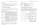
Remark: 

(1)  t1: ENA must be ahead of DIR by at least  5us, logic HIGH as valid.  Generally  

ENA+ and ENA- is NC (not connected). 

(2)  t2: DIR must be ahead of PUL effective falling edge by 5us to ensure correct direction; 

(3)  t3: Pulse width not less than 1.2us; 

(4)  t4: low level width not less than 1.2us. 


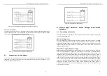
11. Wire Connection 

(1)  In order to improve driver noise rejection, it is recommended to use twist ed 

pair shield cable. 

(2)  To prevent noise incurred in pulse/dir signal, Pulse/direction signal wires 

and motor wires should not be tied up together.  It is better to separate 

them by at least 10 cm, otherwise the motor noise will easily disturb pulse 

direction signals, motor position error, system instability and other types of 

failure. 

(3)  If a power supply serves several drivers, separate connections drivers is 

recommended instead of daisy-chaining. 

(4)  It is prohibited to pull and plug connector P2 while driver is powered ON, 

as there is still high current flowing through coil even when motor is 

stopped.    Pulling and plugging P2 with power on will cause extremely high 

voltage surge EMF, destroy the dirver. 


M

M

D

D

2

2

2

2

7

7

8

8


H

H

i

i

g

g

h

h


P

P

e

e

r

r

f

f

o

o

r

r

m

m

a

a

n

n

c

c

e

e


M

M

i

i

c

c

r

r

o

o

s

s

t

t

e

e

p

p

p

p

i

i

n

n

g

g


D

D

r

r

i

i

v

v

e

e

r

r


V

V

1

1

.

.

0

0


                                                      15 


TWELVE MONTH LIMITED WARRANTY                                               

FULLING MOTOR 

Co., Ltd. warrants its products against defects in materials and 

workmanship for a period of 12 months from receipt by the end-user. During the warranty period, 

FULLING

 will either, at its option, repair or replace products which prove to be defective. 


EXCLUSIONS                                                                                                                           

The above warranty shall not apply to defects resulting from: improper or inadequate handling by 
customer; improper or inadequate customer wiring; unauthorized modification or misuse; or 
operation outside of the electrical and/or environmental specifications for the product. 


OBTAINING WARRANTY SERVICE                                                                                     

To obtain warranty service, a returned material authorization number (RMA) must be obtained 

from customer service at e-mail: 

 before returning product for service. 

Customer shall prepay shipping charges for products returned to

 FULLING

 for warranty service, 

and 

FULLING

 shall pay for return of products to customer.  


WARRANTY LIMITATIONS                                                                             

FULLING

 makes no other warranty, either expressed or implied, with respect to the product. 

FULLING

 specifically disclaims the implied warranties of merchantability and fitness for a 

particular purpose. Some jurisdictions do not allow limitations on how long and implied warranty 

lasts, so the above limitation or exclusion may not apply to you. However, any implied warranty of 

merchantability or fitness is limited to the 12-month duration of this written warranty. 


Shipping Failed Product                                                                                                     

If your product should fail during the warranty period, e-mail customer service at 


to obtain a returned material authorization number


before returning 

product for service. Please include a written description of the problem along with contact name 

and address. Send failed product to distributor in your area or: 

Changzhou Fulling motor Co.,Ltd

.  

66 Zhujiang Road ChangZhou city JiangSu Province

 China.

 Also enclose information 

regarding the circumstances prior to product failure. 


Summary of Contents for MD2278

Page 1: ...bility function or design FULLING does not assume any liability arising out of the application or use of any product or circuit described herein neither does it convey any license under its patent rights of others FULLING s general policy does not recommend the use of its products in life support or aircraft applications wherein a failure or malfunction of the product may directly threaten life or...

Page 2: ... voltage AC80 250V TTL compatible inputs Automatic idle current reduction Output current up to 7 8A peak RMS 5 57A Input frequency up to 400KHz Opto isolated inputs Microstep resolution pulse per rotation selectable vary from 400 500 600 800 1000 1200 1600 2000 2400 3200 4000 5000 6000 6400 8000 and 10000 Suitable for any 2 phase stepping motor with 4 6 8 leads DIP switch current setting CW CCW mo...

Page 3: ...A Enable signal this signal is used for enable disable high level for enabling driver and low level for disabling driver Usually left unconnected enabled READY Output alarm signal positive READY is a photocouper output from open collector circuit effectively output when driver operate normally maximum permitted input voltage 30VDC maximum output current 20mA generally can be serial connected to PL...

Page 4: ... output current Figure 4 8 Lead Motor Series Connections M MD D2 22 27 78 8 H Hi ig gh h P Pe er rf fo or rm ma an nc ce e M Mi ic cr ro os st te ep pp pi in ng g D Dr ri iv ve er r V V1 1 0 0 7 Parallel Connection An 8 lead motor in a parallel configuration offers a more stable but lower torque at lower speeds But because of the lower inductance there will be higher torque at higher speeds Multip...

Page 5: ...nce Maximum Voltage Input The power MOSFETS inside the driver can actually operate within 80 220VAC including power input fluctuation and back EMF voltage generated by motor coils during motor shaft deceleration Higher voltage will damage the driver Therefore it is suggested to use power supplies with theoretical output voltage of no more than 220V leaving room for power line fluatuation and Back ...

Page 6: ...ly sufficiently high supply voltage for intended applications Setting Proper Output Current a For a given motor higher driver current will make the motor to output more torque but at the same time causes more heating in the motor and driver Therefore output current is generally set to be such that the motor will not overheat for long time operation b Since parallel and serial connections of motor ...

Page 7: ...d short circuit protection To improve reliability the driver incorporates a number of built in protections features a Over voltage protection and short voltage protection When power supply voltage exceeds 250VAC protection will be activated and power indicator LED will turn red When power supply voltage is lower than 80VAC the driver will not works properly b Coil ground Short Circuit Protection P...

Page 8: ...end user During the warranty period FULLING will either at its option repair or replace products which prove to be defective EXCLUSIONS The above warranty shall not apply to defects resulting from improper or inadequate handling by customer improper or inadequate customer wiring unauthorized modification or misuse or operation outside of the electrical and or environmental specifications for the p...

Reviews: