background image

23

The Jarvis L-shaped frame accommodates a large main top of 
27” to 33” deep and 54.25” to 82” wide. 

In our experience, desks have better lateral stability the further 
apart the legs are. We position the screw holes for the Side 
Brackets 2 inches in from the sides of the desktop. This leaves 
about 1” of desktop overhang and maximizes lateral stability.

Placing the holes at least 2 inches in from the sides lowers the 
chance that your desktop will split during drilling.Depending on 
the rigidity and strength of your desktop material you can leave 
more of it overhanging the Side Brackets. For example, on our 
78” tops the Side Bracket holes are 5” in from the edge with 4” 
of overhang.

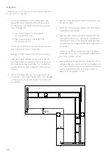
Large “Main” Top

The dimension limits for the smaller top are a little trickier, since 
they’ll depend on the size and shape of your larger top. The total 
distance from the back edge of the large top to the front edge of 
the small top should be between 54.25” and 82”. You can find 
the maximum width of the small top (the side perpendicular to 
the front edge of the large top) by subtracting the depth of the 
large top from 82”. The depth of the small top (the edge parallel 
to the front of the larger top) should be no fewer than 27”, and 
no more than 33”.

For example, if your large desktop is 32” deep, your small 
desktop must be between 24.25” and 50” wide.

Small “Return” Top

Position over the feet

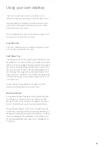
Using your own desktop

There’s no one right way to position your frame on your 
desktop but there are a few things you’ll want to keep in mind. 

Generally speaking, the desktop should be centered over the 
frame side-to-side, and positioned slightly forward of center 
(towards the user) front-to-back. 

Most L-shaped desktops will consist of 2 pieces: a large “main” 
top and a smaller “return” top on one side.

Summary of Contents for Jarvis

Page 1: ...Jarvis L shaped standing desk Assembly instructions For assembly assistance visit fully com instructions contact us at 888 508 3725 or support fully com ...

Page 2: ...Thank you for choosing a Jarvis desk from Fully ...

Page 3: ...3 Cautions and use Contact Before starting Specs In the box Assembly Initial calibration reset Custom settings Using your own desktop 4 4 5 5 6 8 21 22 23 ...

Page 4: ...ay result in physical damage Cautions Voltage converters Using a voltage converter could cause damage to the desk and is considered improper use Resulting damage is not covered by the warranty Verify the voltage of the Control Box as labeled to avoid damage Alternative voltage Control Boxes are available from Fully Use liability This Jarvis height adjustable desk has electric motors and is designe...

Page 5: ...rm that nothing is missing Reference the included parts listings on page 6 Before starting If you are using your own desktop refer to page 16 for instructions before beginning assembly Using your own desktop Tools 3mm Hex Wrench 4mm Hex Wrench Phillips Screwdriver not included 5mm Hex Wrench ...

Page 6: ...ate x2 Q Cable Clip x15 S Frame End Frame End with Capture Plate Corner Frame End A Corner Frame End B I J K L Corner Bracket N Left Side Bracket B Right Side Bracket A Wood Screw x24 T U Large Machine Screw x4 Medium Machine Screw x12 Small Machine Screw x14 Thick Machine Screw x8 V W X Noise Attenuation Grommet x10 Extra AC Box 1 Box 2 AA Desktop Screw x16 for all other work surfaces Z Desktop S...

Page 7: ...7 Not to scale Large Desktop Small Desktop AD AE Desktop Screw x16 Extra AF Desktop boxes 2 ...

Page 8: ... The Handset placed on your left during assembly will be on the right once the desk is flipped over and vice versa The following instructions show the assembly of a desk as shown in configuration 2 below the smaller desktop will be on the left and the Handset will be on the right mounted to the larger desktop We ll point out the steps where you ll need to make adjustments for other orientations 1 ...

Page 9: ...9 J W C J x4 W C x1 3 2 W I C x4 W C x1 I 4 mm 4 mm ...

Page 10: ...10 4 A V 2 A x2 V 2 4 mm B V 3 B x2 V 3 5 4 mm ...

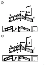
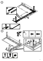
Page 11: ...11 6 K P W AB x2 W P K x2 AB 4 mm x2 U 6 L 7 U L 6 4 mm ...

Page 12: ...12 x2 U 8 x2 AB U N AB 7 N 4 mm 9 Q x2 x8 T AE Q T 1 4 3 2 AD ...

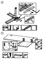
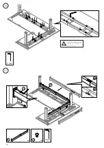
Page 13: ...13 11 10 4 9 Y Z AA OR 4 x4 AA 9 M O M x2 O Y x4 x4 Z Use black screws with bamboo work surfaces Use silver screws with all other work surfaces Use wood screws if you have your own desktop ...

Page 14: ...14 12 11 8 8 11 13 Y Z AA OR Z x5 x5 Z x5 AA Use black screws with bamboo work surfaces Use silver screws with all other work surfaces Use wood screws if you have your own desktop ...

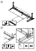
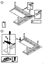
Page 15: ...15 15 14 O 5 x2 O 5 Y Z AA OR Z x5 x5 Z x5 AA Use black screws with bamboo work surfaces Use silver screws with all other work surfaces Use wood screws if you have your own desktop ...

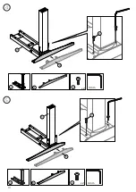
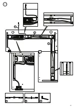
Page 16: ...16 16 17 X R R x2 5 mm x8 X 3 mm Tighten pre installed screws Skipping this step will result in stability issues ...

Page 17: ...17 19 18 3 mm T E E x2 T Tighten pre installed screws Skipping this step will result in stability issues ...

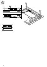
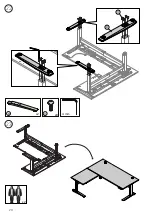
Page 18: ...18 20 F F ...

Page 19: ...19 21 G G H G x2 H x15 S ...

Page 20: ...20 22 23 V D V x8 4 mm x2 D x2 ...

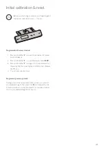
Page 21: ...ds RESET 3 Press and hold the icon again this time until Jarvis first lowers slightly then rises slightly and finally stops Release the icon 4 You can now use your Jarvis To program your memory presets raise or lower your Jarvis to your preferred height Then press the M icon followed by one of the four numbers you want to preset This number will return Jarvis to your preferred height from now on P...

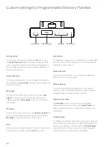
Page 22: ...l Jarvis gets to the memory preset height To calibrate your handset s height display lower Jarvis all the way down and then use a tape measure to determine the height from the top of your desktop to the floor Select the Calibrate height menu option and use the 5 and 6 icons to adjust the height readout to match your previously measured height To lock Jarvis and prevent any further changes to the h...

Page 23: ... on the size and shape of your larger top The total distance from the back edge of the large top to the front edge of the small top should be between 54 25 and 82 You can find the maximum width of the small top the side perpendicular to the front edge of the large top by subtracting the depth of the large top from 82 The depth of the small top the edge parallel to the front of the larger top shoul...

Page 24: ...he larger Side Bracket 2 from the edge and the front most hole at least 6 75 from the front of your desktop The easiest way to accurately position the Frame on the Top is to use the Frame as a guide 4 Slide the Center Rails into the open Frame End from the Corner Assembly 5 Create the final Frame End assembly with the remaining Frame End and Side Bracket 6 Slide this new assembly onto the Center R...

Page 25: ...25 ...

Page 26: ...version 40000492V C Everything you need to find your work flow ...

Reviews: