4
Part # FA100 HEPA Filter
The HEPA filter is 99.97% efficient in removing particles as small as 0.3
µ
from an airstream.
Particles of this size are respirable and can cause significant respiratory problems.
Replacement:
A HEPA’s service life is determined by the volume of sub-micron particles remaining in the airstream after
passing through the pre-filters. When properly protected, and depending on loading, HEPA filters often provide
months of service.
Average service life is 2-4 months.
Part # FA101D Gas/Odor Filter
Most process plumes contain several gases, some odorous – some not, some toxic at elevated concentrations –
some completely harmless regardless of concentration. To ensure employee safety the type and concentration
of pollutants must be determined. Please contact Fumex Engineering for filter selection assistance. These filters
utilize a blended activated carbon and activated alumina impregnated with KMnO4 filter to capture and treat
gases/odors. This combination of materials provides protection across a broad range of gases commonly found
in industrial manufacturing processes.
G E N E R A L M A I N T E N A N C E
1) The blower motor is a sealed unit, 24,000 hr. MTBF rated. It is permanently lubricated and does not require
oiling – keep it free of dust accumulations to prevent overheating.
2) Remove any loose accumulations of dust/debris from the air filter chamber periodically.
“This product employs overload protection (fuse). A blown fuse indicates an overload or short-circuit situation. If
the fuse blows, unplug the product from the outlet. Replace the fuse as per the user servicing instructions (only
10-Amp fuse) and check the product. If the replacement fuse blows, a short circuit may be present and the
product should be discarded or returned to an authorized service facility for examination and/or repair”.
Remote Interface and Connectivity Function
The FA1 can be supplied with an optional interface package providing remote start/stop and filter monitoring
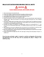
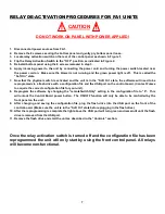
capabilities (Part # FA228). Please see instructions below for Relay Activation/De-Activation procedures and
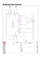
refer to the drawing in Figure 1 for remote connections.
WARNING
“To Prevent the Risk of Electrical Shock, Connect Remote Interface
Cable to 24v, Class 2 Power Supply Only”
WARNING
“Disconnect From All Power Supplies Before Servicing”

