8-3
A91F3TR
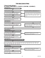
See FLOW CHART No.9
See FLOW CHART No.9
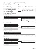
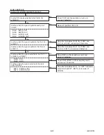
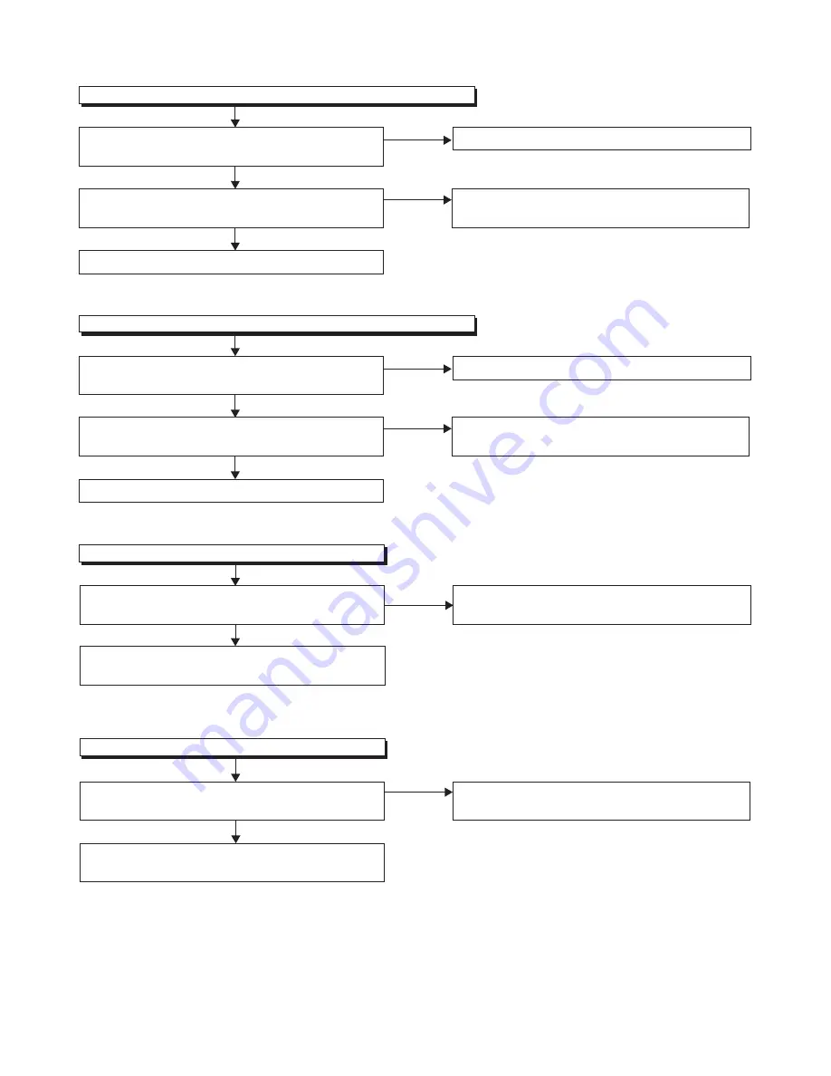
AL+13V(M+13V) is not output.
FLOW CHART NO.12
Yes
No
Is approxi13V voltage supplied to the
cathode of D641 and D642?
Check C639, D642 and their periphery circuit, and
service it if defective.
Check if there is any leak or short-circuit on
the loaded circuit, and service it if defective.
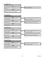
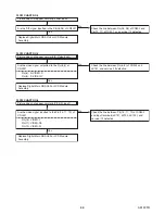
P-ON+5V is not output. (LCD+16V is outputted normally.)
FLOW CHART NO.10
Is approxi6.8V voltage supplied to the
collector of Q643?
Is approxi6V voltage supplied to the
base of Q641 and the base of Q643?
No
Yes
Yes
Check D645 and their periphery circuit, and service
it if defective.
No
Replace Q641 and Q643.
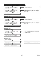
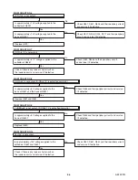
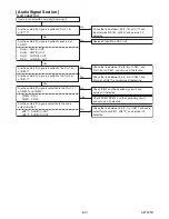
P-ON+5V(TUNER+5V) is not output. (LCD+16V is outputted normally.)
FLOW CHART NO.11
Is approxi6.7V voltage supplied to the
collector of Q640?
Is approxi6V voltage supplied to the
base of Q641 and the base of Q643(Q640)?
No
Yes
Yes
Check D645 and their periphery circuit, and service
it if defective.
No
Replace Q641 and Q643(Q640).
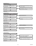
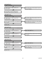
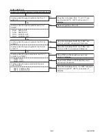
P-ON+3V is not output.
FLOW CHART NO.13
Is approxi3V voltage supplied to the
cathode of D647?
Yes
No
Check if there is any leak or short-circuit on
the loaded circuit, and service it if defective.
Check C645, D647 and their periphery circuit, and
service it if defective.
Summary of Contents for 32MF339B/F7
Page 63: ...10 8 A91FSSCM2 Power Supply 2 4 Schematic Diagram LC321SSX 32MF369B F7 ...
Page 64: ...10 9 A91FSSCM3 Power Supply 3 4 Jack Schematic Diagram LC321SSX 32MF369B F7 ...
Page 65: ...10 10 A91FSSCM4 Power Supply 4 4 Schematic Diagram LC321SSX 32MF369B F7 ...
Page 68: ...10 13 A91F3SCF Function Schematic Diagram LC320SLX 32MF339B F7 LC320SSX LC320EMX LC320EMXF ...
Page 69: ...10 14 A91FSSCF Function Schematic Diagram LC321SSX 32MF369B F7 ...
Page 71: ...10 16 A91FSSCIR IR Sensor Junction Schematic Diagram LC321SSX 32MF369B F7 ...

