1-6-4
E9G01DC
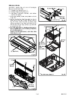
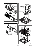
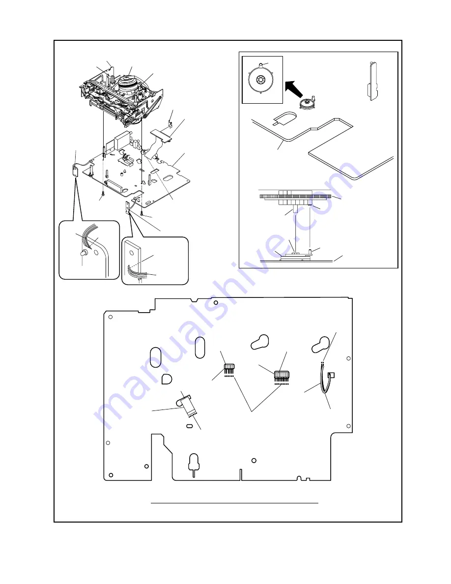
[19] Main CBA
(with AFV CBA)
[15] Deck
Assembly
[16] Power
SW CBA
[17] Function CBA
FE Head
Cylinder
Assembly
ACE Head
Assembly
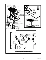
Desolder
Lead with
blue stripe
[19] Main CBA
[19] Main CBA
SW507
LD-SW
From
FE Head
BOTTOM VIEW
Lead connections of Deck Assembly and Main CBA
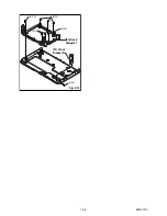
Desolder
From
Capstan
Motor
Assembly
Printing side
Desolder
From
Cylinder
Assembly
From
ACE Head
Assembly
Lead with
blue stripe
Lead with
blue stripe
Desolder
Lead with
gray stripe
(S-17)
(S-18)
Desolder
Lead
with
blue
stripe
Fig. D9
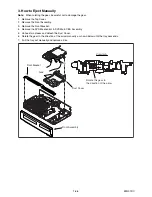
LD-SW
Pin
Hole
Hole
Shaft
Cam Gear
[15] Deck Assembly
Pin
Desolder
from bottom
[18] Rear Jack
CBA
21P Earth Plate
Summary of Contents for DRVR-B778S
Page 17: ...1 6 5 E9G01DC Fig D10 20 Deck Pedestal 21 Front Bracket R S 19 S 19 S 19 S 19 S 20...
Page 56: ...1 13 3 E9G10SCM1 Main 1 9 Schematic Diagram VCR Section...
Page 58: ...1 13 5 E9G10SCM3 Main 3 9 Schematic Diagram VCR Section...
Page 59: ...1 13 6 E9G10SCM4 Main 4 9 Schematic Diagram VCR Section...
Page 60: ...1 13 7 E9G10SCM5 Main 5 9 Schematic Diagram VCR Section...
Page 61: ...1 13 8 E9G10SCM6 Main 6 9 Front Jack Schematic Diagram VCR Section...
Page 62: ...1 13 9 E9G10SCM7 Main 7 9 Schematic Diagram VCR Section...
Page 63: ...1 13 10 E9G10SCM8 Main 8 9 Schematic Diagram VCR Section...
Page 64: ...1 13 11 E9G10SCM9 Main 9 9 Schematic Diagram VCR Section...
Page 66: ...1 13 13 E9G10SCRJ Rear Jack Schematic Diagram VCR Section...
Page 67: ...1 13 14 E9G10SCAFV AFV Schematic Diagram VCR Section...
Page 87: ...1 18 2 E9G01PEX Packing X4 S2 S2 S3 S2 A14 S1 S5 S5 S2 X9 X3 S9 X2 X1 X31 X43 X22 X20 S10...
Page 104: ...DRVR B778S E9G10BD 2007 07 23...

