1-11-4
E9G01TR
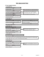
2 DVD Section
Yes
No
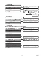
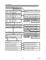
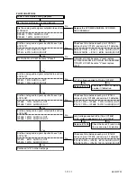
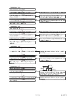
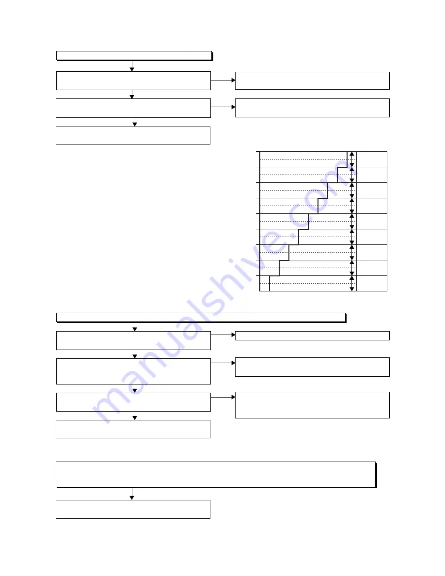
FLOW CHART NO.1
The key operation is not functioning.
Are the contact point and the installation state of
the key switches normal?
Is the control voltage normally inputted into Pin(8)
of IC501?
Check the key switches and their periphery, and
service it if defective.
No
Re-install the key switches correctly or replace
the poor switch.
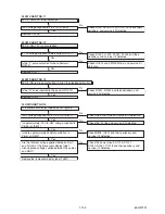
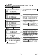
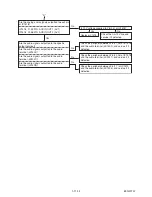
FLOW CHART NO.2
No DVD operation is possible from the remote control unit. (Operation is possible from the unit.)
Replace the RM1501 (remote control receiver).
Replace remote control unit if needed.
Check the line between the RM1501 (remote
control receiver) and Pin(14) of IC501, and
service it if defective.
Is the "L" pulse sent out from Pin(1) terminal of the
RM1501 (remote control receiver) when the remote
control unit is activated?
Is the "L" pulse signal supplied to Pin(14) of
IC501?
Replace IC501 or DVD MECHANISM & DVD
MAIN CBA ASSEMBLY.
Yes
Yes
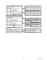
Replace IC501 or DVD MECHANISM & DVD
MAIN CBA ASSEMBLY.
Yes
Is 5V voltage supplied to Pin(3) terminal of the
RM1501 (remote control receiver)?
Yes
No
Check AL+5V line, and service it if defective.
No
No
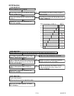
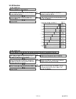
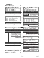
0.51
0.92
1.27
1.61
1.98
2.39
2.90
3.60
4.30
SENS-
INH
-----
REC
/OTR
OPEN/
CLOSE
DUBBING
PLAY
STOP
-----
-----
Terminal voltage of IC501-8
KEY-2
IC501-8
(V)
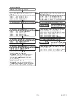
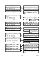
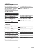
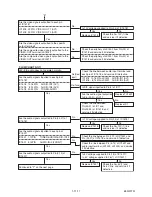
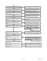
FLOW CHART NO.3
Replace the DVD MECHANISM & DVD MAIN
CBA ASSEMBLY.
The [No Disc] indication.
Both picture and sound do not operate normally.
Summary of Contents for DRVR-B778S
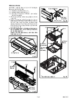
Page 17: ...1 6 5 E9G01DC Fig D10 20 Deck Pedestal 21 Front Bracket R S 19 S 19 S 19 S 19 S 20...
Page 56: ...1 13 3 E9G10SCM1 Main 1 9 Schematic Diagram VCR Section...
Page 58: ...1 13 5 E9G10SCM3 Main 3 9 Schematic Diagram VCR Section...
Page 59: ...1 13 6 E9G10SCM4 Main 4 9 Schematic Diagram VCR Section...
Page 60: ...1 13 7 E9G10SCM5 Main 5 9 Schematic Diagram VCR Section...
Page 61: ...1 13 8 E9G10SCM6 Main 6 9 Front Jack Schematic Diagram VCR Section...
Page 62: ...1 13 9 E9G10SCM7 Main 7 9 Schematic Diagram VCR Section...
Page 63: ...1 13 10 E9G10SCM8 Main 8 9 Schematic Diagram VCR Section...
Page 64: ...1 13 11 E9G10SCM9 Main 9 9 Schematic Diagram VCR Section...
Page 66: ...1 13 13 E9G10SCRJ Rear Jack Schematic Diagram VCR Section...
Page 67: ...1 13 14 E9G10SCAFV AFV Schematic Diagram VCR Section...
Page 87: ...1 18 2 E9G01PEX Packing X4 S2 S2 S3 S2 A14 S1 S5 S5 S2 X9 X3 S9 X2 X1 X31 X43 X22 X20 S10...
Page 104: ...DRVR B778S E9G10BD 2007 07 23...

