1-11-5
E9G01TR
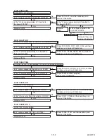
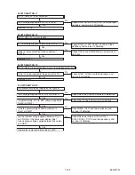
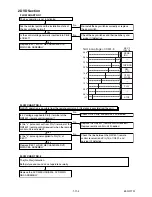
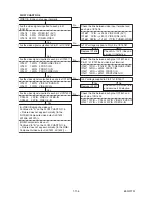
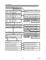
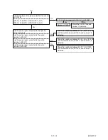
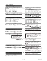
FLOW CHART NO.4
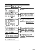
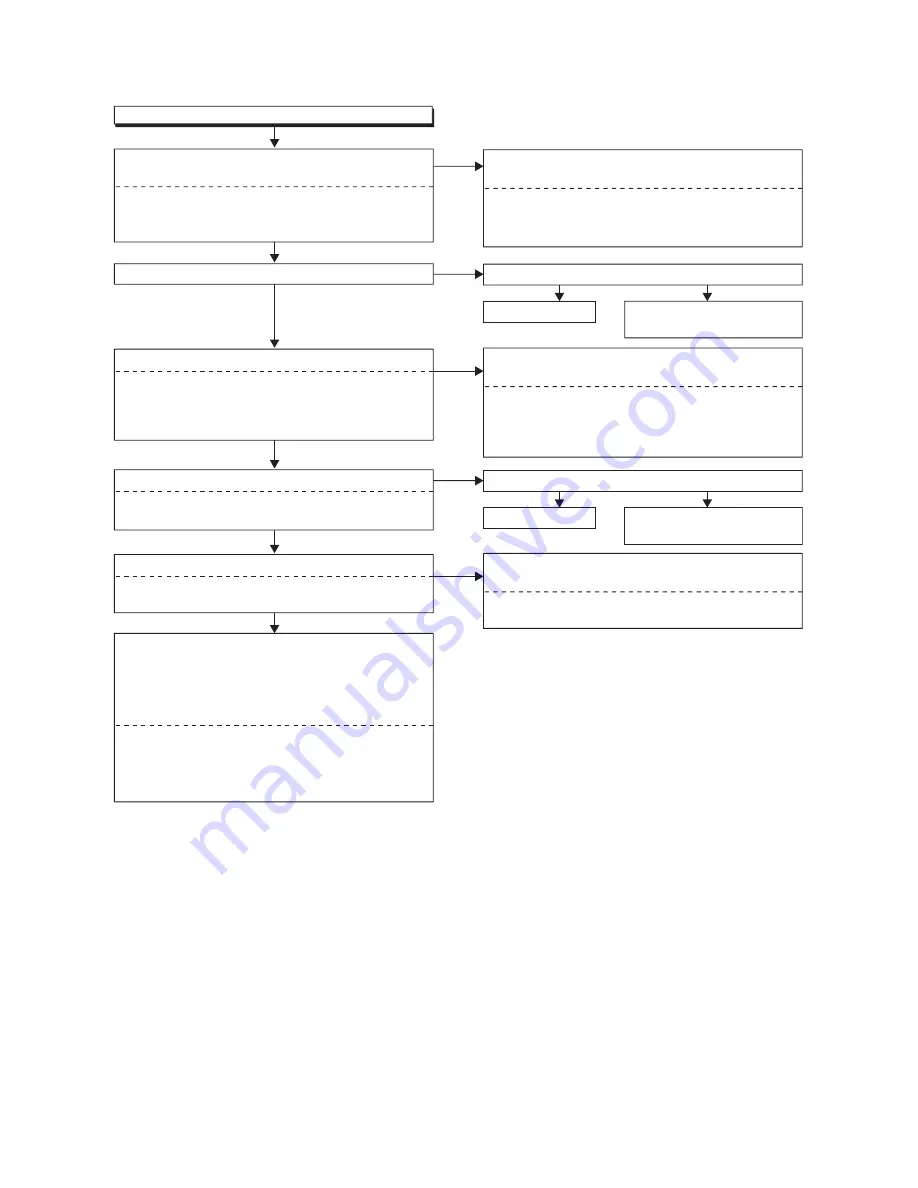
VIDEO E-E does not appear normally.
Are the video signals inputted to each pin of
IC1518?
Check the line between video input terminal and
each pin of IC1518.
IC1581 1PIN
→
JK1502 VIDEO-IN1 (AV1)
IC1581 3PIN
→
JK2001 VIDEO-IN2 (AV2)
IC1581 28PIN
→
TU1501 17PIN TUNER-VIDEO
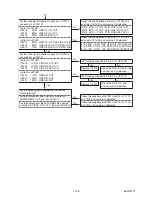
Check the line between each pin of IC1507 and
Pin(31) of IC1518 and video input terminal.
IC1507 12PIN
→
IC1518 31PIN TUNER/LINE VIDEO
IC1507 15PIN
→
JK1204 FRONT-Y-IN
IC1507 4PIN
→
JK1204 FRONT-C-IN
IC1507 10PIN
→
JK1201 FRONT-VIDEO-IN
Are the video signals inputted to each pin of IC1507?
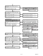
(S-VIDEO/Composite video out)
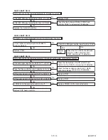
Continued to "A" on the FLOW CHART NO. 5.
< Picture does not appear normally. [In the
S-VIDEO/Composite video output (JK1502,
JK1506, JK2001)] >
(RGB/Component video out)
Continued to "B" on the FLOW CHART NO. 6.
< Picture does not appear normally. [In the RGB/
Component video output (JK1501, JK1502)] >
Yes
Yes
No
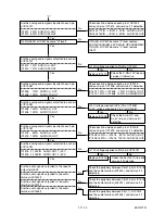
Is 12V voltage supplied to Pin(2,4) of IC1518?
No
No
IC1518 1PIN VIDEO-IN1 (AV1)
IC1518 3PIN VIDEO-IN2 (AV2)
IC1518 28PIN TUNER-VIDEO
IC1507 12PIN TUNER/LINE VIDEO
IC1507 15PIN FRONT-Y-IN
IC1507 4PIN FRONT-C-IN
IC1507 10PIN FRONT-VIDEO-IN
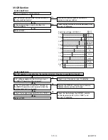
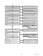
Check the line between each pin of IC1507 and
each pin of CN1502.
IC1507 19PIN
→
CN1502 20PIN VIDEO-Y/CVBS-IN
IC1507 21PIN
→
CN1502 22PIN VIDEO-C-IN
Are the video signals inputted to each pin of CN1502?
Yes
No
CN1502 20PIN VIDEO-Y/CVBS-IN
CN1502 22PIN VIDEO-C-IN
Are the video signals outputted to each pin of IC1507?
Yes
IC1507 19PIN VIDEO-Y/CVBS-IN
IC1507 21PIN VIDEO-C-IN
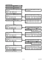
Are the video signals outputted to Pin(31) of IC1518?
Yes
Replace IC1518.
No
Check AL+12V(1) line and
service it if defective.
Yes
Is 5V voltage supplied to Pin(1) of IC1507?
No
Replace IC1507.
No
Check DVD-P-ON+5V line
and service it if defective.
Yes
Summary of Contents for DRVR-B778S
Page 17: ...1 6 5 E9G01DC Fig D10 20 Deck Pedestal 21 Front Bracket R S 19 S 19 S 19 S 19 S 20...
Page 56: ...1 13 3 E9G10SCM1 Main 1 9 Schematic Diagram VCR Section...
Page 58: ...1 13 5 E9G10SCM3 Main 3 9 Schematic Diagram VCR Section...
Page 59: ...1 13 6 E9G10SCM4 Main 4 9 Schematic Diagram VCR Section...
Page 60: ...1 13 7 E9G10SCM5 Main 5 9 Schematic Diagram VCR Section...
Page 61: ...1 13 8 E9G10SCM6 Main 6 9 Front Jack Schematic Diagram VCR Section...
Page 62: ...1 13 9 E9G10SCM7 Main 7 9 Schematic Diagram VCR Section...
Page 63: ...1 13 10 E9G10SCM8 Main 8 9 Schematic Diagram VCR Section...
Page 64: ...1 13 11 E9G10SCM9 Main 9 9 Schematic Diagram VCR Section...
Page 66: ...1 13 13 E9G10SCRJ Rear Jack Schematic Diagram VCR Section...
Page 67: ...1 13 14 E9G10SCAFV AFV Schematic Diagram VCR Section...
Page 87: ...1 18 2 E9G01PEX Packing X4 S2 S2 S3 S2 A14 S1 S5 S5 S2 X9 X3 S9 X2 X1 X31 X43 X22 X20 S10...
Page 104: ...DRVR B778S E9G10BD 2007 07 23...

