


8-3
FL10.1TR
See FLOW CHART No.8
TUNER+5V is not output. (PANEL+13V is outputted normally.)
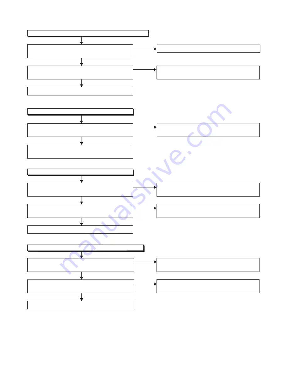
FLOW CHART NO.10
Is approxi6.7V voltage supplied to the
collector of Q637?
Is approxi6V voltage supplied to the
base of Q637?
No
Yes
Yes
Check D659 and their periphery circuit, and service
it if defective.
No
Replace Q637.
P-ON+3.3V(PANEL+3.3V) is not output.
FLOW CHART NO.12
Is approxi5V voltage supplied to the
cathode of D639?
Is the "H" signal (approxi3.5V) inputted to the
base of Q640?
No
Yes
Yes
Check C639, D639 and their periphery circuit, and
service it if defective.
Check Q638, Q639, P-ON-H2 line and their periphery
circuit, and service it if defective.
No
FLOW CHART NO.13
Replace Q640.
P-ON+3V is not output.
FLOW CHART NO.11
Is approxi3V voltage supplied to the
cathode of D638?
Yes
No
Check if there is any leak or short-circuit on
the loaded circuit, and service it if defective.
Check C638, D638 and their periphery circuit, and
service it if defective.
P-ON+9V is not output. (PANEL+13V is outputted normally.)
Is approxi13V voltage supplied to the
collector of Q641?
Is approxi10V voltage supplied to the
base of Q641?
No
Yes
Yes
Check D666 and their periphery circuit, and service
it if defective.
Check C643, D643 and their periphery circuit,
and service it if defective.
No
Replace Q641.
Summary of Contents for FL10.1
Page 14: ...4 2 FL10 1DC 2 Rear Cabinet S 1 1 Stand Assembly S 2 S 2 S 5 S 2 S 4 S 3 S 2 S 2 S 2 Fig D1...
Page 39: ...10 3 FL10 1SCM1 Main 1 Schematic Diagram...
Page 40: ...10 4 FL10 1SCM2 Main 2 Schematic Diagram...
Page 41: ...10 5 FL10 1SCM3 Main 3 Junction B Schematic Diagram...
Page 43: ...10 7 FL10 1SCJ Jack Junction C Schematic Diagram...
Page 44: ...10 8 FL10 1SCF Function Junction A Schematic Diagram...


