8-5
FL10.1TR
[ Video Signal Section ]
No
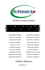
Is the "L" pulse sent out Pin(1) terminal of remote
control receiver (RS101) when the infrared remote
control is activated?
Check the line between Pin(1) terminal of remote
control receiver(RS101) and Pin(25) of CN301,
and service it if defective.
Yes
Is the "L" pulse supplied to Pin(25) of CN301?
Yes
Is 3.3V voltage supplied to Pin(2) terminal of the
remote control receiver (RS101)?
No
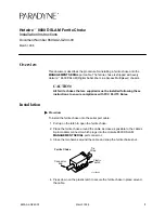
FLOW CHART NO.2
Operation is possible from the unit.
Check AL+3.3V line and service it if defective.
No
Replace the remote control receiver(RS101)
or the remote control unit.
Yes
Replace Digital Main CBA Unit.
When pressing each switches (SW104~SW109)
do the voltage of Pin(29) of CN302 increase?
Yes
The key operation is not functioning.
FLOW CHART NO.1
Are the contact point and installation state of the key
switches (SW104~SW109) normal?
Re-install the switches (SW104~SW109) correctly
or replace the poor switch.
Check the switches (SW104~SW109) and their
periphery, and service it if defective.
Yes
Replace Digital Main CBA Unit.
No
No
No operation is possible from the remote control unit.
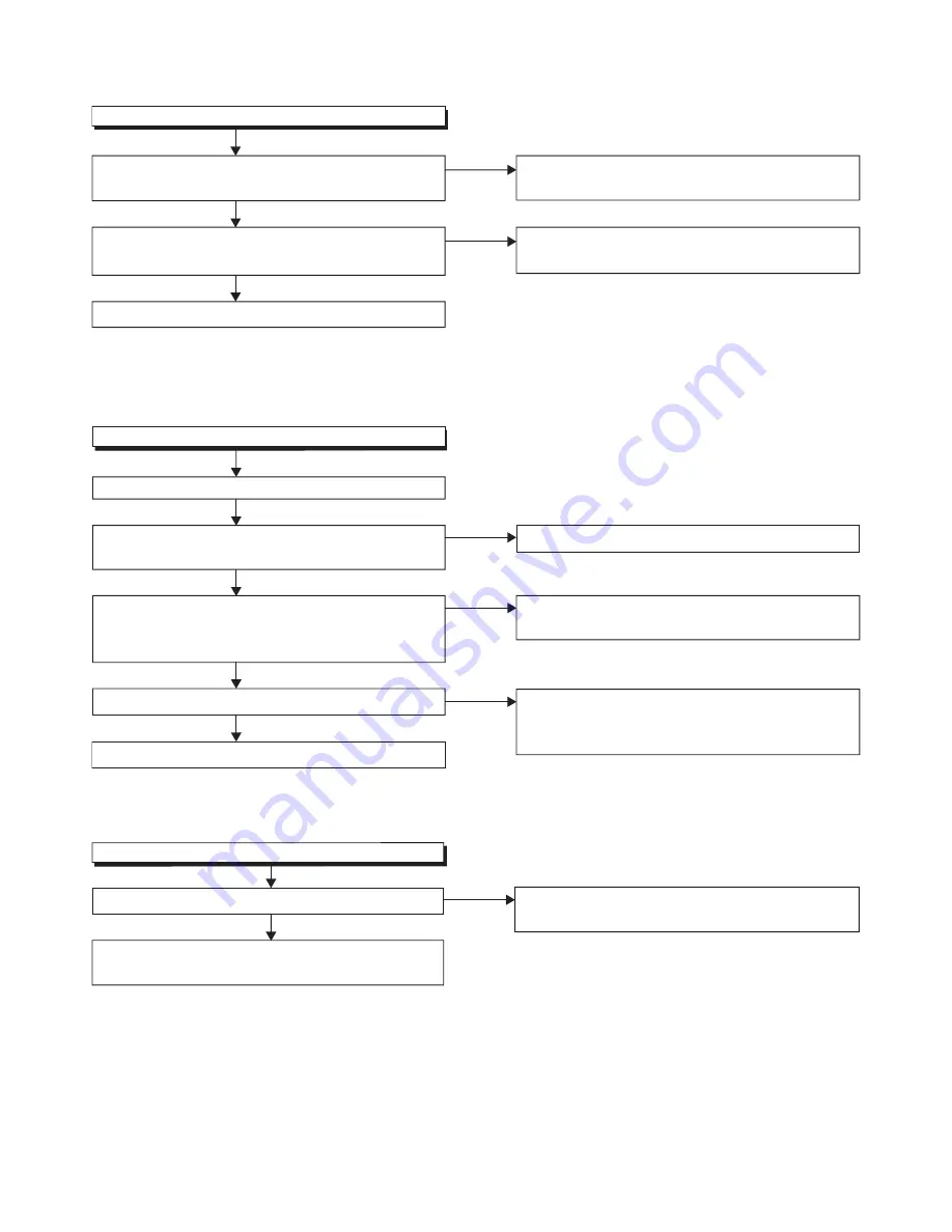
Picture does not appear normally.(Video input)
FLOW CHART NO.3
Are the video signal inputted to Pin(4) of CN302?
Yes
Check the line between Pin(4) of CN302 and
JK752, and service it if defective.
No
Replace Digital Main CBA Unit or LCD Module
Assembly.
Summary of Contents for FL10.1
Page 14: ...4 2 FL10 1DC 2 Rear Cabinet S 1 1 Stand Assembly S 2 S 2 S 5 S 2 S 4 S 3 S 2 S 2 S 2 Fig D1...
Page 39: ...10 3 FL10 1SCM1 Main 1 Schematic Diagram...
Page 40: ...10 4 FL10 1SCM2 Main 2 Schematic Diagram...
Page 41: ...10 5 FL10 1SCM3 Main 3 Junction B Schematic Diagram...
Page 43: ...10 7 FL10 1SCJ Jack Junction C Schematic Diagram...
Page 44: ...10 8 FL10 1SCF Function Junction A Schematic Diagram...