1-7-2
E3TFGDC
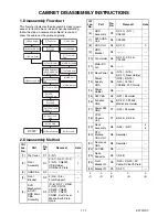
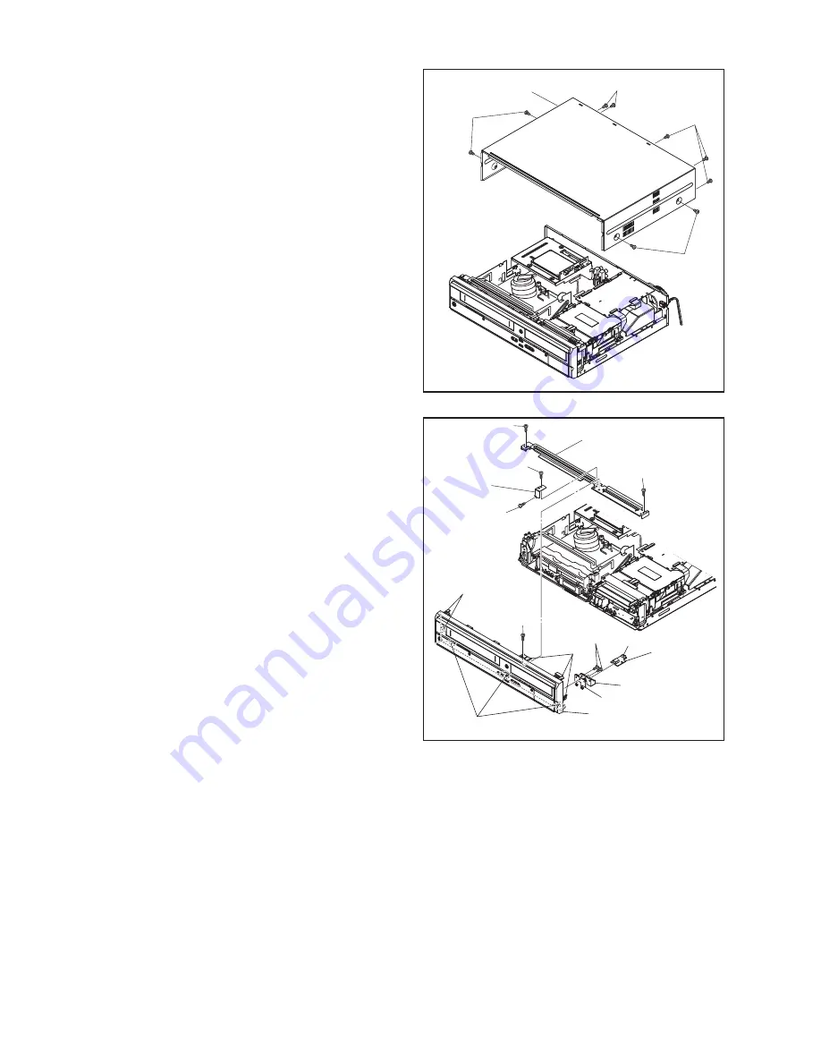
Note:
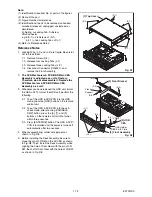
(1): Identification (location) No. of parts in the figures
(2): Name of the part
(3): Figure Number for reference
(4): Identification of parts to be removed, unhooked,
unlocked, released, unplugged, unclamped, or
desoldered.
P=Spring, L=Locking Tab, S=Screw,
CN=Connector
e.g. 6(S-1) = six Screws of (S-1),
5(L-1) = five Locking Tabs of (L-1)
(5): Refer to “Reference Notes.”
Reference Notes
1. Locking Tabs (L-1) and (L-2) are fragile. Be careful
not to break them.
1-1. Remove Screw (S-2).
1-2. Release four Locking Tabs (L-1).
1-3. Release three Locking Tabs (L-2).
1-4. Disconnect Connector (CN6001), and
remove the Front Assembly.
2.
The DVD Mechanism & DVD/HDD Main CBA
Assembly is adjusted as a unit at factory.
Therefore, do not disassemble it. Replace the
DVD Mechanism & DVD/HDD Main CBA
Assembly as a unit.
3. Whenever you have replaced the HDD unit, format
the HDD unit. To format the HDD unit, perform the
following.
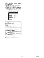
3-1. To put the HDD & DVD/VCR into the HDD
mode, press the [HDD] button on the remote
control unit.
3-2. To put the HDD & DVD/VCR into the self-
check mode, after pressing [VARIABLE
SKIP] button, press the [0], [7], and [9]
buttons on the remote control in that order
within three seconds.
3-3. Press [ENTER/OK] button. The HDD & DVD/
VCR is formatted and the power is turned off
automatically after two seconds.
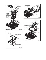
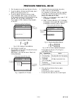
4. When reassembling, solder wire jumpers as
shown in Fig. D8.
5. Before installing the Deck Assembly, be sure to
place the pin of LD-SW on the AV CBA as shown
in Fig. D8. Then, install the Deck Assembly while
aligning the hole of Cam Gear with the pin of LD-
SW, the shaft of Cam Gear with the hole of LD-SW
as shown in Fig. D8.
(S-1)
(S-1)
(S-1)
(S-1)
[1] Top Cover
Fig. D1
(L-1)
(L-2)
(L-1)
(S-5)
(S-4)
(S-2)
Front
Support
USB Holder
CN6001
USB Earth Plate
[2] Front Assembly
[3] USB
CBA
[4] Front Bracket
(S-4)
(S-4)
(S-3)
Fig. D2
Summary of Contents for TD6D-M101
Page 61: ...1 15 3 E3TFGSCAV1 AV 1 10 Schematic Diagram VCR Section...
Page 63: ...1 15 5 E3TFGSCAV3 AV 3 10 Schematic Diagram VCR Section...
Page 64: ...1 15 6 E3TFGSCAV4 AV 4 10 Schematic Diagram VCR Section...
Page 65: ...1 15 7 E3TFGSCAV5 AV 5 10 Schematic Diagram VCR Section...
Page 66: ...1 15 8 E3TFGSCAV6 AV 6 10 Schematic Diagram VCR Section...
Page 67: ...1 15 9 E3TFGSCAV7 AV 7 10 Schematic Diagram VCR Section...
Page 68: ...1 15 10 E3TFGSCAV8 AV 8 10 Schematic Diagram VCR Section...
Page 69: ...1 15 11 E3TFGSCAV9 AV 9 10 Schematic Diagram VCR Section...
Page 70: ...1 15 12 E3TFGSCAV10 AV 10 10 Schematic Diagram VCR Section...
Page 73: ...1 15 15 Rear Jack Schematic Diagram VCR Section E3TFGSCRJ...
Page 79: ...1 15 21 E3TFGSCD6 DVD HDD Main 6 7 Schematic Diagram DVD HDD Section...
Page 81: ...1 15 23 E3TFGSCDTV DTV Module Schematic Diagram DVD HDD Section...
Page 82: ...1 15 24 E3TFGSCSATA SATA Schematic Diagram...
Page 107: ...TD6D M101 E3TFGEH 2013 04 22...


