1-12-1
E3TF0FIS
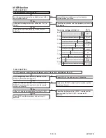
FUNCTION INDICATOR SYMBOLS
< VCR Section >
Note:
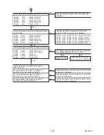
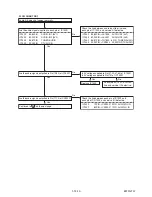
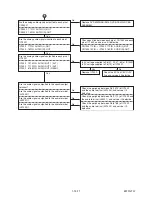
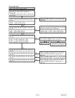
If a mechanical malfunction occurs, the power is turned off. Turn the power back on by pressing [STANDBY-
ON] button and an error message will be displayed on the TV screen for 5 seconds
TV screen
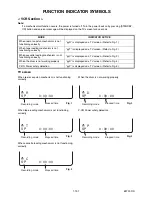
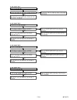
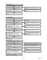
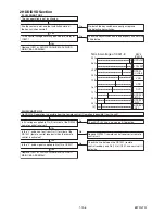
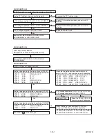
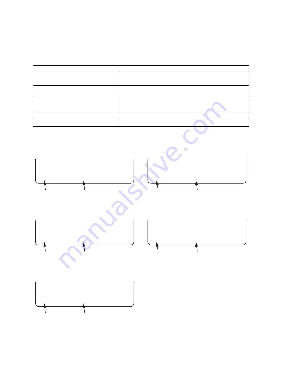
When reel or capstan mechanism is not functioning
correctly
When tape loading mechanism is not functioning
correctly
When cassette loading mechanism is not functioning
correctly
When the drum is not working properly
P-ON Power safety detection
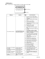
MODE
INDICATOR ACTIVE
When reel or capstan mechanism is not
functioning correctly
“
A
R” is displayed on a TV screen. (Refer to Fig. 1.)
When tape loading mechanism is not
functioning correctly
“
A
T” is displayed on a TV screen. (Refer to Fig. 2.)
When cassette loading mechanism is not
functioning correctly
“
A
C” is displayed on a TV screen. (Refer to Fig. 3.)
When the drum is not working properly
“
A
D” is displayed on a TV screen. (Refer to Fig. 4.)
P-ON Power safety detection
“
A
P” is displayed on a TV screen. (Refer to Fig. 5.)
A
R
SP 0 : 00 : 00
Recording mode
Elapsed time
Fig. 1
A
T
SP 0 : 00 : 00
Recording mode
Elapsed time
Fig. 2
A
C
SP 0 : 00 : 00
Recording mode
Elapsed time
Fig. 3
A
D
SP 0 : 00 : 00
Recording mode
Elapsed time
Fig. 4
A
P
SP 0 : 00 : 00
Recording mode
Elapsed time
Fig. 5
Summary of Contents for TD6D-M101
Page 61: ...1 15 3 E3TFGSCAV1 AV 1 10 Schematic Diagram VCR Section...
Page 63: ...1 15 5 E3TFGSCAV3 AV 3 10 Schematic Diagram VCR Section...
Page 64: ...1 15 6 E3TFGSCAV4 AV 4 10 Schematic Diagram VCR Section...
Page 65: ...1 15 7 E3TFGSCAV5 AV 5 10 Schematic Diagram VCR Section...
Page 66: ...1 15 8 E3TFGSCAV6 AV 6 10 Schematic Diagram VCR Section...
Page 67: ...1 15 9 E3TFGSCAV7 AV 7 10 Schematic Diagram VCR Section...
Page 68: ...1 15 10 E3TFGSCAV8 AV 8 10 Schematic Diagram VCR Section...
Page 69: ...1 15 11 E3TFGSCAV9 AV 9 10 Schematic Diagram VCR Section...
Page 70: ...1 15 12 E3TFGSCAV10 AV 10 10 Schematic Diagram VCR Section...
Page 73: ...1 15 15 Rear Jack Schematic Diagram VCR Section E3TFGSCRJ...
Page 79: ...1 15 21 E3TFGSCD6 DVD HDD Main 6 7 Schematic Diagram DVD HDD Section...
Page 81: ...1 15 23 E3TFGSCDTV DTV Module Schematic Diagram DVD HDD Section...
Page 82: ...1 15 24 E3TFGSCSATA SATA Schematic Diagram...
Page 107: ...TD6D M101 E3TFGEH 2013 04 22...

