1-13-15
E3TFGTR
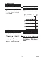
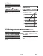
D-FG
D-PG
5Vp-p
2.5Vp-p
D-FG
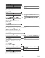
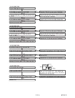
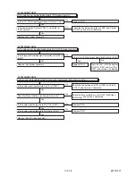
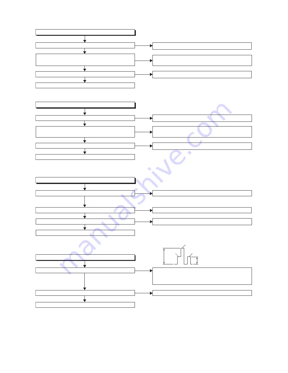
FLOW CHART NO.6
Capstan Motor does not rotate.
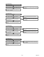
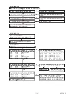
FLOW CHART NO.7
Drum Motor does not rotate.
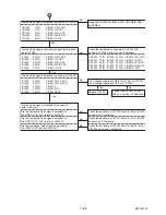
FLOW CHART NO.8
Drum Motor rotates only for a few seconds.
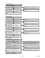
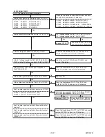
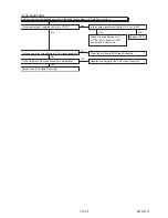
FLOW CHART NO.9
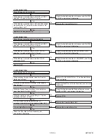
RF-SW signal is not outputted.
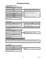
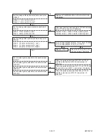
Is the Drum Motor rotating?
Is 5V voltage supplied to Pin(2) of CN502?
Is 12V voltage supplied to Pin(1) of CN502?
Is over approximately 2.6V voltage supplied to Pin(5)
of CN502?
Check the P-ON+5V line and service it if defective.
Check the line between Pin(5) of CN502 and Pin(76) of
IC501, and service it if defective.
Check AL+16V/+12V line, and service it if defective.
Check the AL+12V line, and service it if defective.
Check the AL+12V line, and service it if defective.
Check the P-ON+5V line and service it if defective.
Check the line between Pin(8) of CN502 and Pin(77) of
IC501, and service it if defective.
Replace IC501.
No
No
No
No
No
No
No
No
No
No
No
Yes
Yes
Yes
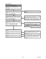
Is 5V voltage supplied to Pin(2) of CN502?
Is the D-PFG signal inputted to Pin(90) of IC501?
Is the D-PFG signal inputted to Pin(90) of IC501?
Is 12V voltage supplied at Pin(11) of CN502?
Is the RF-SW signal outputted to Pin(18) of IC501?
Is 12V voltage supplied Pin(11) of CN 502?
Replace the Capstan Motor or the Cylinder Assembly.
Replace the Capstan Motor or the Cylinder Assembly.
Refer to "FLOW CHART NO.7" <Drum Motor does
not rotate> and "FLOW CHART NO.8" <Drum Motor
rotates only for a few seconds>.
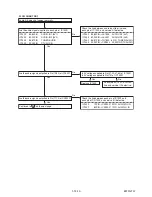
Is over approximately 2.6V voltage supplied to
Pin(8) of CN502?
Yes
Yes
Yes
Yes
Replace IC501.
Replace the Capstan Motor or the Cylinder Assembly.
Yes
Yes
Yes
Yes
Replace the Capstan Motor.
Replace the Capstan Motor or the Cylinder Assembly.
Summary of Contents for TD6D-M101
Page 61: ...1 15 3 E3TFGSCAV1 AV 1 10 Schematic Diagram VCR Section...
Page 63: ...1 15 5 E3TFGSCAV3 AV 3 10 Schematic Diagram VCR Section...
Page 64: ...1 15 6 E3TFGSCAV4 AV 4 10 Schematic Diagram VCR Section...
Page 65: ...1 15 7 E3TFGSCAV5 AV 5 10 Schematic Diagram VCR Section...
Page 66: ...1 15 8 E3TFGSCAV6 AV 6 10 Schematic Diagram VCR Section...
Page 67: ...1 15 9 E3TFGSCAV7 AV 7 10 Schematic Diagram VCR Section...
Page 68: ...1 15 10 E3TFGSCAV8 AV 8 10 Schematic Diagram VCR Section...
Page 69: ...1 15 11 E3TFGSCAV9 AV 9 10 Schematic Diagram VCR Section...
Page 70: ...1 15 12 E3TFGSCAV10 AV 10 10 Schematic Diagram VCR Section...
Page 73: ...1 15 15 Rear Jack Schematic Diagram VCR Section E3TFGSCRJ...
Page 79: ...1 15 21 E3TFGSCD6 DVD HDD Main 6 7 Schematic Diagram DVD HDD Section...
Page 81: ...1 15 23 E3TFGSCDTV DTV Module Schematic Diagram DVD HDD Section...
Page 82: ...1 15 24 E3TFGSCSATA SATA Schematic Diagram...
Page 107: ...TD6D M101 E3TFGEH 2013 04 22...

