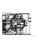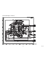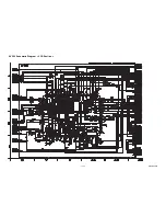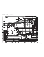
1-14-9
E3TFGBLP
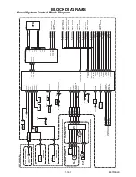
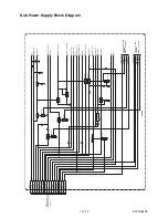
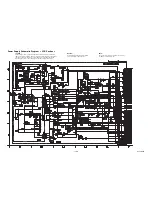
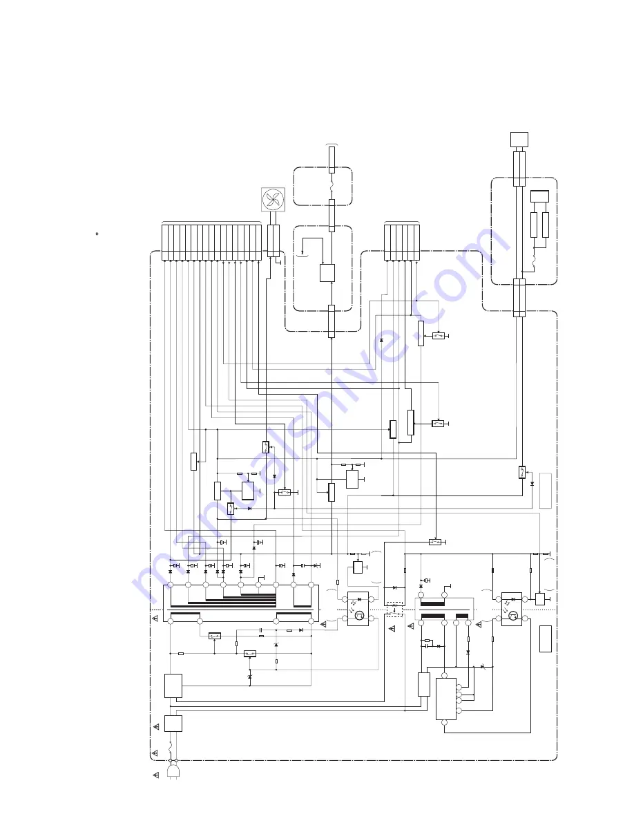
Power Supply Block Diagram
CAUTION !
Fixed voltage (or Auto voltage selectable) power supply circuit is used in this unit.
If Main Fuse (F1001) is blown , check to see that all components in the power supply
circuit are not defective before you connect the AC plug to the AC power supply.
Otherwise it may cause some components in the power supply circuit to fail.
NOTE:
The voltage for parts in hot circuit is measured using
hot GND as a common terminal.
CAUTION !
For continued protection against fire hazard,
replace only with the same type fuse.
NOTE:
Either IC3607 or IC3608 is used for FUNCTION CBA.
USB CB
A
AC1001
F1001
T2.5A H 250V
LINE
FILTER
L1003
D1001 - D1004
BRIDGE
RECTIFIER
3
5
Q1001
Q1003
Q1107
Q1109
Q1114
TO SUB
POWER SUPPLY
BLOCK DIAGRAM
(CN1503)
TO DIGITAL SIGNAL
PROCESS BLOCK
DIAGRAM
Q1102
Q1104
Q1119
7
8
3
4
IC1001
ERROR
VOLTAGE DET
ERROR
VOLTAGE DET
IC1101
T1001
POWER SUPPLY CBA
HOT CIRCUIT. BE CAREFUL.
18
17
16
15
14
13
12
11
10
CL1001
CN1001
CN1002
Q1100
Q1101
Q1106
SW+5V
SHUNT
REG.
IC1102
HIGH
SIDE
SW
*IC3607
*IC3608
SATA
I/F
IC5001
HO
T
COLD
IC1103
+3.3V REG.
IC1104
IC5002
FAN
SHUNT
REG.
IC1190
HARD
DISK
DRIVE
1
2
SW+12V
Q1112
SW+5V
SW+5V
+1.8V REG.
TO
DVD/HDD
MAIN CBA
(CN101)
USB
JACK
11
+5V
CN6005
CN3605
44
USB+5V
CN3604
1
USB+5V
CN6002
CN6001
V-
B
U
S
FUNCTION CB
A
13
HDD+12V
31
HDD+5V
20-22
HDD+12V
14-16
HDD+5V
CN1003
CN5002
CN5003
SA
T
A
CB
A UNIT
1
F
AN+12V
2
GND
F6001
1A
F5001
630mA
+3.3V REG.
IC5003
+1.8V REG.
25-27
P-ON+10.5V
20-22
P-ON+5V
10-12
AL+2.8V
6,7
P-ON+1.8V
15-17
P-ON+3.3V
1
1V2CONT
11
MAIN-ON
32
P-ON+3.3V
30,31
AL+2.8V
27
REG-CONT
29
PO
W
-SW
34
LA
TCH-UP
10
1V2CONT
23
F2
24
F1
26
SYS+5V
15,16
AL+5V
13,14
D
V
D-P-ON+5V
12
P-ON+10V
6,7
AL+12V
2,3
AL+16.3V
1
AL+44V
22
AL-30V
IC1051
3
4
IC1052
ERROR
VOLTAGE DET
1
3
5
6
T1051
9
8
D1051-D1054
(SWITCHING)
FB
VDD
S
S
D
CL
RL1001
RECTIFIER
IC1151
5
2
4
8
7
1
Q1051
REG
ERROR
VOLTAGE DET
1
2
REG
Summary of Contents for TD6D-M101
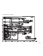
Page 61: ...1 15 3 E3TFGSCAV1 AV 1 10 Schematic Diagram VCR Section...
Page 63: ...1 15 5 E3TFGSCAV3 AV 3 10 Schematic Diagram VCR Section...
Page 64: ...1 15 6 E3TFGSCAV4 AV 4 10 Schematic Diagram VCR Section...
Page 65: ...1 15 7 E3TFGSCAV5 AV 5 10 Schematic Diagram VCR Section...
Page 66: ...1 15 8 E3TFGSCAV6 AV 6 10 Schematic Diagram VCR Section...
Page 67: ...1 15 9 E3TFGSCAV7 AV 7 10 Schematic Diagram VCR Section...
Page 68: ...1 15 10 E3TFGSCAV8 AV 8 10 Schematic Diagram VCR Section...
Page 69: ...1 15 11 E3TFGSCAV9 AV 9 10 Schematic Diagram VCR Section...
Page 70: ...1 15 12 E3TFGSCAV10 AV 10 10 Schematic Diagram VCR Section...
Page 73: ...1 15 15 Rear Jack Schematic Diagram VCR Section E3TFGSCRJ...
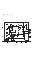
Page 79: ...1 15 21 E3TFGSCD6 DVD HDD Main 6 7 Schematic Diagram DVD HDD Section...
Page 81: ...1 15 23 E3TFGSCDTV DTV Module Schematic Diagram DVD HDD Section...
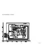
Page 82: ...1 15 24 E3TFGSCSATA SATA Schematic Diagram...
Page 107: ...TD6D M101 E3TFGEH 2013 04 22...

