1-16-1
TD6PWF
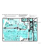
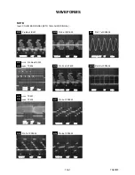
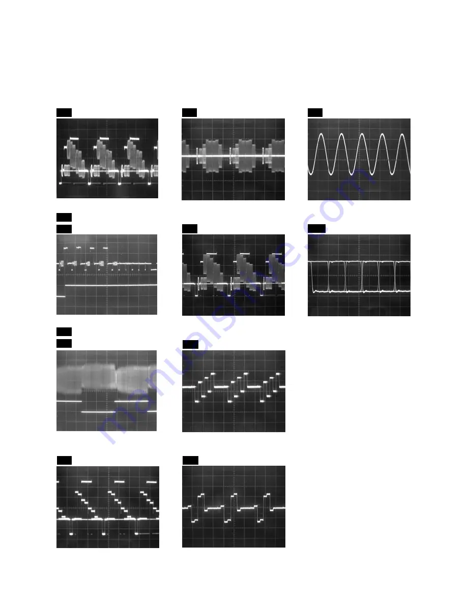
WAVEFORMS
WF9
AUDIO(L)-OUT
Pin 17 of CN1502
1V
0.5ms
WF7
VIDEO-Cb
Pin 3 of CN1502
0.2V
20
µ
s
WF8
VIDEO-Cr
Pin 5 of CN1502
0.2V
20
µ
s
SPDIF
1V
0.1
µ
s
WF10
Pin 28 of CN1503
WF4
Pin 7 of CN1502
VIDEO-Y
0.2V
20
µ
s
WF5
Pin 9 of CN1502
VIDEO-C
0.2V
20
µ
s
WF6
Pin 30 of IC1509
VIDEO-CVBS
0.5V
20
µ
s
NOTE:
Input: COLOR BAR SIGNAL (WITH 1KHz AUDIO SIGNAL)
WF3
WF1
UPPER
WF2
WF2
LOWER
TP504
UPPER
LOWER
TP504
TP301
V-OUT
0.5V
50
µ
s
RF-SW
5V
C-PB
RF-SW
5V
5ms
0.2V
WF1
Pin 56 of IC301
V-OUT E-E
0.2V
20
µ
s
Pin 56 of IC301
Summary of Contents for TD6D-M101
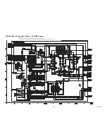
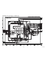
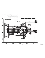
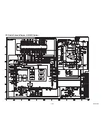
Page 61: ...1 15 3 E3TFGSCAV1 AV 1 10 Schematic Diagram VCR Section...
Page 63: ...1 15 5 E3TFGSCAV3 AV 3 10 Schematic Diagram VCR Section...
Page 64: ...1 15 6 E3TFGSCAV4 AV 4 10 Schematic Diagram VCR Section...
Page 65: ...1 15 7 E3TFGSCAV5 AV 5 10 Schematic Diagram VCR Section...
Page 66: ...1 15 8 E3TFGSCAV6 AV 6 10 Schematic Diagram VCR Section...
Page 67: ...1 15 9 E3TFGSCAV7 AV 7 10 Schematic Diagram VCR Section...
Page 68: ...1 15 10 E3TFGSCAV8 AV 8 10 Schematic Diagram VCR Section...
Page 69: ...1 15 11 E3TFGSCAV9 AV 9 10 Schematic Diagram VCR Section...
Page 70: ...1 15 12 E3TFGSCAV10 AV 10 10 Schematic Diagram VCR Section...
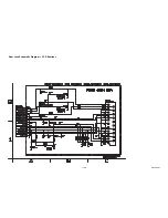
Page 73: ...1 15 15 Rear Jack Schematic Diagram VCR Section E3TFGSCRJ...
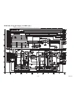
Page 79: ...1 15 21 E3TFGSCD6 DVD HDD Main 6 7 Schematic Diagram DVD HDD Section...
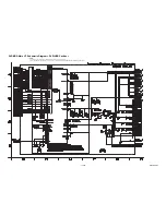
Page 81: ...1 15 23 E3TFGSCDTV DTV Module Schematic Diagram DVD HDD Section...
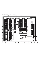
Page 82: ...1 15 24 E3TFGSCSATA SATA Schematic Diagram...
Page 107: ...TD6D M101 E3TFGEH 2013 04 22...

