1-3-2
T6600STA
1.2. Standard solder
e. Soldering Iron
Use a pencil-type soldering iron (less than 30
watts).
f. Solder
Eutectic solder (Tin 63%, Lead 37%) is recom-
mended.
g. Soldering time
Do not apply heat for more than 4 seconds.
h. Preheating
Leadless capacitor must be preheated before
installation. (130°C~150°C, for about two minutes.)
Notes:
a. Leadless components must not be reused after
removal.
b. Excessive mechanical stress and rubbing for the
component electrode must be avoided.
2. Removing the leadless component
Grasp the leadless component body with tweezers
and alternately apply heat to both electrodes. When
the solder on both electrodes has melted, remove
leadless component with a twisting motion.
Notes:
a. Do not attempt to lift the component off the board
until the component is completely disconnected
from the board by the twisting action.
b. Take care not to break the copper foil on the printed
board
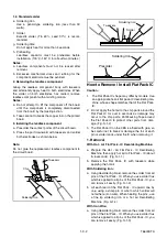
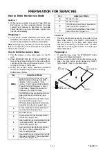
3. Installing the leadless component
a. Presolder the contact points of the circuit board.
b. Press the part downward with tweezers and solder
both electrodes as shown below.
Note:
Do not glue the replacement leadless component to
the circuit board.
How to Remove / Install Flat Pack IC
Caution:
1.
The Flat Pack-IC shape may differ by models. Use
an appropriate hot-air flat pack-IC desoldering ma-
chine, whose shape matches that of the Flat Pack-
IC.
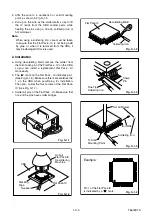
2. Do not apply the hot air to the chip parts around the
Flat Pack-IC for over 6 seconds as damage may
occur to the chip parts. Put Masking Tape around
the Flat Pack-IC to protect other parts from dam-
age. (Fig. S-1-2)
3. The Flat Pack-IC on the CBA is affixed with glue, so
be careful not to break or damage the foil of each
pin or solder lands under the IC when removing it.
1. Removal
With Hot - Air Flat Pack - IC Desoldering Machine:
a. Prepare the Hot - Air Flat Pack - IC Desoldering
Machine, then apply hot air to Flat Pack - IC (about
5~6 seconds). (Fig. S-1-1)
b. Remove the Flat Pack- IC with tweezers while
applying the hot air.
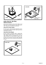
With Soldering Iron:
a. Using desoldering braid, remove the solder from all
pins of the Flat Pack - IC. When you use solder flux
which is applied to all pins of the Flat Pack - IC, you
can remove it easily. (Fig. S-1-3)
b. Lift each lead of the Flat Pack - IC upward one by
one, using a sharp pin or wire to which solder will
not adhere (iron wire). When heating the pins, use
a fine tip soldering iron or a hot air Desoldering
Machine. (Fig. S-1-4)
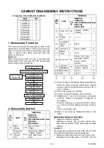
With Iron Wire:
a. Using desoldering braid, remove the solder from all
pins of the Flat Pack - IC. When you use solder flux
which is applied to all pins of the Flat Pack - IC, you
can remove it easily. (Fig. S-1-3)
Chip
Tweezers
Soldering Iron
Soldering Iron
Tweezers
Solder
Soldering Iron
Presolder
Summary of Contents for TVCR-2104
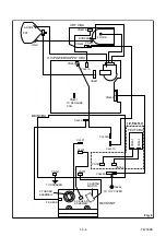
Page 17: ...1 5 4 T6700DC Fig 4 S 11 S 11 S 11 S 11 Anode Cap 11 CRT CRT CBA...
Page 37: ...Main 2 5 Schematic Diagram 1 8 5 1 8 6 T6700SCM2...
Page 42: ...1 8 15 1 8 16 H V Power Supply 2 2 Schematic Diagram T6700SCP2...
Page 43: ...1 8 17 1 8 18 T6700SCCRT CRT Schematic Diagram...
Page 86: ...2 4 9 Z13PDA Fig DM16 43 41 42 L 13 Fig DM17 44 45 Slide P 9...


