1-6-5
T6700EA
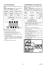
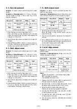
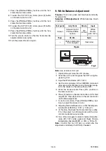
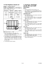
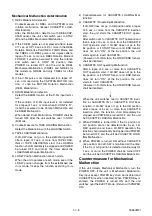
7. Press the [PROG+/PROG-] buttons until the hori-
zontal line becomes white.
8. To enter the CUT OFF (G) mode, press [2] button
on the remote control unit.
9. Press the [PROG+/PROG-] buttons until the hori-
zontal line becomes white.
10.To enter the CUT OFF (B) mode, press [3] button
on the remote control unit.
11.Press the [PROG+/PROG-] buttons until the hori-
zontal line becomes white.
12.Turn the screen control so that the horizontal line
adjusted white looks lightly.
13.Turn the power off and on again.
9. White Balance Adjustment
Purpose:
To mix red, green and blue beams correctly
for pure white.
Symptom of Misadjustment:
White becomes bluish
or reddish.
Note:
Use remote control unit
1. Operate the unit more than 20 minutes.
2. Face the unit to east. Degauss the CRT using De-
gaussing Coil.
3. Input the White Raster (APL 100%).
4. Set the color analyzer to the CHROMA mode and
after zero point calibration, bring the optical recep-
tor to the center on the tube surface (CRT).
5. Enter the Service mode. Press [VOL-] button on
the remote control.
6. Press [4] button on the remote control unit for Red
adjustment. Press [5] button on the remote control
unit for Blue adjustment.
7. In each color mode, Press [PROG+/PROG-] but-
tons to adjust the values of color.
8. Adjusting Red and Blue color so that the tempera-
ture becomes 8500K (x : 290 / y : 300) ±3%.
9. At this time, Re-check that Horizontal line is white.
If not, Re-adjust Cut-off Adjustment until the Hori-
zontal Line becomes pure white.
10. Turn off and on again to return to normal mode. Re-
ceive APL 100% white signal and Check Chroma
temperatures become 8500K (x : 290 / y : 300) ±3%.
Note:
Confirm that Cut Off Adj. is correct after this
adjustment, and attempt Cut Off Adj. if needed.
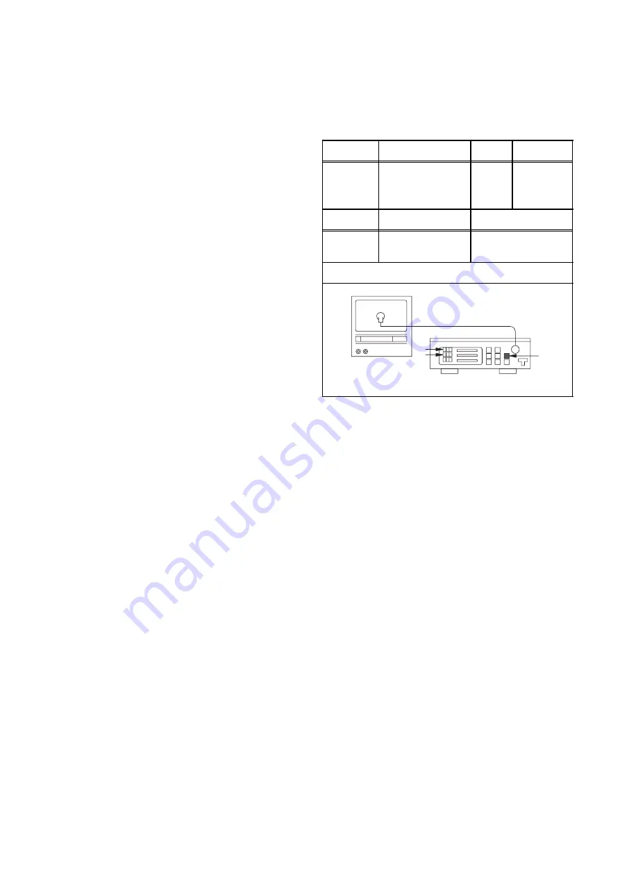
Test point
Adj. Point
Mode
Input
Screen
Screen-Control,
PROG+/PROG-
buttons
RF
(or Ext.)
White
Raster
(APL 100%)
Tape
M. EQ.
Spec.
---
Pattern Generator,
Color analyzer
See below
Figure
Color Ajalyzer
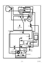
Fig. 5
Summary of Contents for TVCR-2104
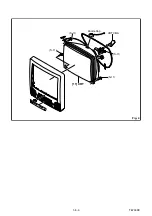
Page 17: ...1 5 4 T6700DC Fig 4 S 11 S 11 S 11 S 11 Anode Cap 11 CRT CRT CBA...
Page 37: ...Main 2 5 Schematic Diagram 1 8 5 1 8 6 T6700SCM2...
Page 42: ...1 8 15 1 8 16 H V Power Supply 2 2 Schematic Diagram T6700SCP2...
Page 43: ...1 8 17 1 8 18 T6700SCCRT CRT Schematic Diagram...
Page 86: ...2 4 9 Z13PDA Fig DM16 43 41 42 L 13 Fig DM17 44 45 Slide P 9...

