1-2-1
T6600SFTY
IMPORTANT SAFETY PRECAUTIONS
Prior to shipment from the factory, our products are strictly inspected for recognized product safety and electrical
codes of the countries in which they are to be sold. However, in order to maintain such compliance, it is equally
important to implement the following precautions when a set is being serviced.
Safety Precautions for TV Circuit
1. Before returning an instrument to the custom-
er,
always make a safety check of the entire instru-
ment, including, but not limited to, the following
items:
a.
Be sure that no built-in protective devices are de-
fective and have been defeated during servicing.
(1) Protective shields are provided on this chassis
to protect both the technician and the customer.
Correctly replace all missing protective shields, in-
cluding any removed for servicing convenience.
(2) When reinstalling the chassis and/or other as-
sembly in the cabinet, be sure to put back in place
all protective devices, including but not limited to,
nonmetallic control knobs, insulating fishpapers,
adjustment and compartment covers/shields, and
isolation resistor/capacitor networks.
Do not oper-
ate this instrument or permit it to be operated
without all protective devices correctly in-
stalled and functioning. Servicers who defeat
safety features or fail to perform safety checks
may be liable for any resulting damage.
b.
Be sure that there are no cabinet openings through
which an adult or child might be able to insert their
fingers and contact a hazardous voltage. Such
openings include, but are not limited to, (1) spac-
ing between the picture tube and the cabinet
mask, (2) excessively wide cabinet ventilation
slots, and (3) an improperly fitted and/or incorrectly
secured cabinet back cover.
c. Antenna Cold Check -
With the instrument AC
plug removed from any AC source, connect an
electrical jumper across the two AC plug prongs.
Place the instrument AC switch in the on position.
Connect one lead of an ohmmeter to the AC plug
prongs tied together and touch the other ohmme-
ter lead in turn to each tuner antenna input ex-
posed terminal screw and, if applicable, to the
coaxial connector. If the measured resistance is
less than 1.0 megohm or greater than 5.2 mego-
hm, an abnormality exists that must be corrected
before the instrument is returned to the customer.
Repeat this test with the instrument AC switch in
the off position.
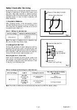
d. Leakage Current Hot Check -
With the instru-
ment completely reassembled, plug the AC line
cord directly into a 120V AC outlet. (Do not use an
isolation transformer during this test.) Use a leak-
age current tester or a metering system that com-
plies with American National Standards Institute
(ANSI) C101.1 Leakage Current for Appliances
and Underwriters Laboratories (UL) 1410, (50.7).
With the instrument AC switch first in the on posi-
tion and then in the off position, measure from a
known earth ground (metal water pipe, conduit,
etc.) to all exposed metal parts of the instrument
(antennas, handle brackets, metal cabinet, screw
heads, metallic overlays, control shafts, etc.), es-
pecially any exposed metal parts that offer an elec-
trical return path to the chassis. Any current
measured must not exceed 0.5 milli-ampere. Re-
verse the instrument power cord plug in the outlet
and repeat the test.
ANY MEASUREMENTS NOT WITHIN THE LIMITS
SPECIFIED HEREIN INDICATE A POTENTIAL
SHOCK HAZARD THAT MUST BE ELIMINATED
BEFORE RETURNING THE INSTRUMENT TO
THE CUSTOMER OR BEFORE CONNECTING
THE ANTENNA OR ACCESSORIES.
e. X-Radiation and High Voltage Limits -
Because
the picture tube is the primary potential source of
X-radiation in solid-state TV receivers, it is special-
ly constructed to prohibit X-radiation emissions.
For continued X-radiation protection, the replace-
ment picture tube must be the same type as the
original. Also, because the picture tube shields
and mounting hardware perform an X-radiation
protection function, they must be correctly in place.
High voltage must be measured each time servic-
DEVICE
LEAKAGE
CURRENT
TESTER
ALSO TEST WITH
PLUG REVERSED
USING AC
ADAPTER PLUG
AS REQUIRED
TEST ALL EXPOSED
METAL SURFACES
READING SHOULD
NOT BE ABOVE 0.5 mA
EARTH
GROUND
BEING
TESTED
Summary of Contents for TVCR-2104
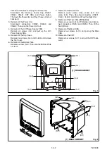
Page 17: ...1 5 4 T6700DC Fig 4 S 11 S 11 S 11 S 11 Anode Cap 11 CRT CRT CBA...
Page 37: ...Main 2 5 Schematic Diagram 1 8 5 1 8 6 T6700SCM2...
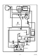
Page 42: ...1 8 15 1 8 16 H V Power Supply 2 2 Schematic Diagram T6700SCP2...
Page 43: ...1 8 17 1 8 18 T6700SCCRT CRT Schematic Diagram...
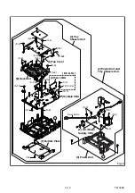
Page 86: ...2 4 9 Z13PDA Fig DM16 43 41 42 L 13 Fig DM17 44 45 Slide P 9...


