© www.funkamateur.de
Automatic Antenna Selector
Housing
12
BX-7300 • 180403
Housing
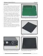
To join the main board and the metal blocks, M3
×
4 cylinder
screws are used while the case housing uses M3
×
4 black
cross head countersunk screws. Next to be assembled are six
metal blocks to the underside and two to the topside of the
board. Attention must be paid that the counter sunk holes on
the blocks are placed facing outwards rather than in, where
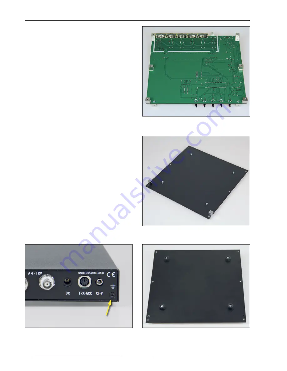
later the housing pieces will be screwed in (pictures 20 and
26).
Two blocks are screwed into the ground plate and also the
four rubber feet, for which we use M3
×
10 cross head
screws, M3 nuts for which M3 washers are provided, the lat-
ter used for augmenting the rubberfoot squashing depth and
serve to give a better bearing surface for the screw head
(picture 28).
Then the front panel and the rear panel with the fixed ele-
ments of the main board are screwed together (don’t forget
the three M3
×
6 with nuts to fix the socket board). Finally
the whole assembly is placed on the ground plate and fixed
with the case housing screws. With the case now open, the
lid should be correctly orientated according to the FA-AS
configuration, and screwed in.
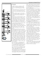
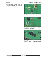
The FA-AS requires an earth connection to the rear panel
(picture 25), for which there is an M3
×
8 crosshead screw a
toothed washer and two M3 plain washers provided, further-
more the kit also comes with a soldering eyelet.
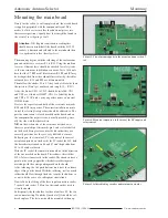
Picture 26. Board underside with the six metal blocks screwed in.
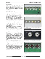
Picture 27. These two blocks on the base plate are used later to
fix the sides.
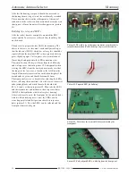
Picture 28. The four rubber feet on the underside of the base
plate are useful later for a steadier stand.
Picture 25. Rear view of the fully built FA- AS; the earth symbol
marks the housing screw which serves as the earthing point.
Summary of Contents for BX-7300
Page 20: ...BX 7300 February 2018...

