© www.funkamateur.de
Automatic Antenna Selector
In use
16
BX-7300 • 180403
band is chosen the FA-AS doesn’t switch. The FA-AS is not
only sent the control signals over the CAT interface, addi-
tional separate instructions are also interpreted wherever
they arrive from. During this (very short) time the LED
flashes blue before thenn remaining lit after the switching.
A plugged in jumper in position 7 of JP2 enables this func-
tion, with an open contact (unplugged) it is disabled.
Drive power in transverter mode
With a jump lead at position 6 one can decide whether the
reduction in output power should be 10 % (open contact) or
1 % (plugged in jumper) of the nominal output power. At the
end of use in transverter mode, the suppressed output power
automatically resets, this, of course, if the FA-AS hasn’t
been switched off.
After finishing the configuration the top cover of the case
must be fixed in place with six countersunk housing screws.
The FA-AS is now ready for operation.
In use
Picture 30 shows the typical wiring layout of the FA-AS in
the shack. Corresponding to the local layout the antennas are
connected to the sockets ANT 1 to ANT 4, an existing trans -
verter to the BNC socket TRV and the transceiver to the SO
239 socket TRX. The same goes for the connection between
FA-AS and transceiver by way of power and, if applicable,
CAT cable.
After turning on the apparatus (DC to socket 7 or socket 8)
the initiallising phase of the software will run. The micro-
processor reads the jumper position on J2 together with the
hexadecimal switches S6 and S7 and sets agreed parameters.
ANT 1 flashes briefly during this before staying lit green.
This checks that the FA-AS has a valid line voltage about
2V connected (30m, 6m or 4m shouldn’t be selected) and
that the transceiver delivers a valid frequency (1.8 …
72MHz). During the line voltage check ANT 2 blinks, dur-
ing the CAT check ANT 3 blinks. Whenever a check is suc-
cessful the requisite LED lights up and stays lit. During
these testing stages no further equipment should be con-
nected to the CAT interface.
Where the software data source has not been recognised or
after about 15 seconds and the checking time threshold has
been reached, this will be shown as 3 flashes, and colour ac-
cording to table 6. (The time threshold installed is quite
long, this is to allow for transceivers that after turning on re-
quire a little time to fully power up). In this phase antennas
will not be selected, only ANT 1 although switched off is as-
sociated with the TRX connection.
Finally, switch the FA-AS, in its required condition, to the
working mode desired (automatic or manual).
Programming the antenna allocations
The allocating of antennas to the selected amateur radio bands
(programming the FA-AS) is thankfully simple. You set up a
band and briefly press the associated buton, ANT 1 to ANT 4
for an antenna slot, then pressing the same button again for
longer than 1 second before letting go. The nearest red LED
lights up briefly then lights up again and changes colour to
green. Thereby the allocation of the antenna to the selected
band is stored. The procedure is to be repeated for all amateur
radio bands. The allocation can be changed at any time.
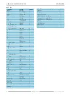
Table 6. Significance of flashing LED’s after running the interface tests.
LED’s after switch on Significance
ANT 1 ANT 2 ANT 3 ANT 4 Line voltage
CIV
Automatic
Manual
present
mode
mode
green green green green yes
yes
×
green green red red yes
no
×
red red green green no
yes
×
red red red red no
no
×
Summary of Contents for BX-7300
Page 20: ...BX 7300 February 2018...

