In use
Automatic Antenna Selector
BX-7300 • 180403
© www.funkamateur.de
17
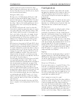
The FA-AS is now set up for automatic mode use and re-
quires no further handling for as long as the transceiver de-
livers valid control signals.
Automatic mode
On selection of a band it automatically switches to the
stored antenna and the associated LED lights up green. After
each band change the FA-AS always selects the last stored
matching antenna. The LED’s light and stay green. A gentle
press of a button temporarily switches the FA-AS and the re-
lated antennas on the transceiver to manual mode (LED’s
light red). After each band change the FA-AS automatically
resets to automatic mode.
Manual mode
In the case of forced manual mode use, on the grounds of
failure of line voltage or CAT data, after powering up the
FA-AS always switches to ANT 1 and the associated LED
lights red. Any of the other antennas may be selected by
pressing the associated button and its LED will light up red.
Transverter mode
The FA-AS offers the possibility by the press of a button to
switch the transceivers antenna connection to the input of a
transverter. After which may follow a checking of the in-
stalled bands and an automatic reduction of transmitter
power so that the transverter input isn’t mistakenly over-
loaded. (Details see paragraph “
Configuration
”). This func-
tion cannot be overidden. The transverter mode is selected
by a short press of the TRV button, then the LED found just
above will light up blue. The LED will flash blue during this
routine. A further press of the TRV button exits the trans -
verter mode and switches the transceiver back to an antenna
according to the selected band.
Further possible applications
antenna. The transverter test routine (see paragraph “
Config-
uration
”) is then completely disconnected. This antenna may
then be selected by a button press although it isn’t available
in automatic mode.
In place of an antenna a load resistance may be connected
which for example, at the press of a button on the
transceiver, may comfortably allow for the conducting of se-
quential measurements.
The FA-AS can also be ‘reversed’ in that it may serve one
antenna yet several transceivers or receivers. Then the an-
tenna is connected to the TRX socket and the sets to the an-
tenna sockets. Selection is possible in manual mode by but-
ton press.
Footnote on use with the CAT interface
The use of the CAT interface is appropriate if the distinction
of the amateur radio bands is too inaccurate based solely on
the line voltage (for instance if the WARC bands or the 60 m
band should be assigned to individual antennas). If the CAT
interface on the transceiver is not yet occupied, it is sufficient
to connect the socket labeled
Remote
with a 3.5 mm jack
cable to the CI-V socket of the FA-AS and to observe the
corresponding notes in the previous sections.
If the interface is already occupied by one or more other de-
vices (for example PC with control or logbook program), the
working mode of the CAT interface of the FA-AS should be
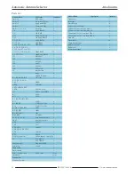
adapted accordingly. This is done by putting a jumper on po-
sition 8 of pin header J2. After restarting the FA-AS, it will
no longer operate in active transmit-receive mode (S / E)
with respect to CI-V, but in passive receive mode (E), see
also Table 5. This means that the FA-AS will use the Inter-
face only "overheard" and only then reacts when other con-
nected devices exchange frequency data. Data collisions on
the interface, which would otherwise be unavoidable when
querying the transceiver operating data, can no longer occur.
For the transceiver to send the current frequency data to the
CI-V interface during manual tuning (and the FA-AS can
"hear" something), its CAT interface must be set to
TRCV On
via the setup menu. It is of course important to ensure that all
connected devices work at the same baud rate.
Note: In this working mode of the CAT interface it is also
possible to cascade several FA-AS and thus switch over more
than four antennas. Each additional device adds three anten-
nas. (One connection is needed to loop through the RF sig-
nal.)
Have fun and enjoy building and using the FA-AS automatic
antenna selector.
shop@funkamateur.de
Literatur:
[1] Schmücking, P., DL7JSP: Antennenumschalter FA-AS für IC-7300 &
Co. FUNKAMATEUR 65 (2016) H. 12, S. 1153 –1157
[2] Reichelt Elektronik GmbH & Co. KG, Elektronikring 1, 26452 Sande,
Tel. (04422) 955-333, Fax -111;
www.reichelt.de
Summary of Contents for BX-7300
Page 20: ...BX 7300 February 2018...

