BX-7300 • 180403
© www.funkamateur.de
5
Automatic Antenna Selector
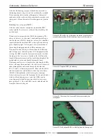
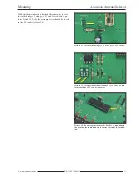
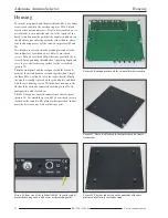
Hex code switch
Push button switches
Circuit
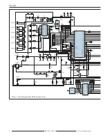
Central to the circuit is a microprocessor PIC
16F887 in a 40 pin DIL housing. Its defined
firmware is essential to the operation of the de-
vice.
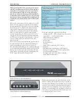
For the antenna and transceiver connections there
are five SO 239 sockets provided on the rear of
the FA-AS along with a BNC socket for the trans -
verter.
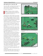
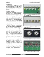
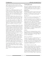
HF parts (delineated in picture 2 with a dotted
line) and control electronics are found on the same
board and isolated from each other by metal
screening.
In the case of non-selection, the respective outer
conductors make no circuit connection to the re-
maining sockets. This prevents adjustment prob-
lems that could occur where the coax cable of the
not selected antennas starts working as a random
additional counterpoise to the active antenna.
Were this considered unnecessary then the separat-
ing gap between the contact points on the socket
board could subsequently bridge over.
In the stand by state, the outer conductor of the
connected cables is short circuited with the match-
ing inner conductor. As long as the FA-AS is
switched off the transceiver associates with an-
tenna 1.
The SWR at the end of the connected antennas
feed line should be up to about 3, within a certain
range that otherwise the transceivers antenna tuner
can’t match, in any case, higher values on account
of extra co ax cable attenuation are unfavourable.
For the switching element there is the 12V power
relay K1 to K5. Controlled by IC2 this takes its
control commands over a serial interface with IC1.
As well, on the rear of the FA-AS there is a sepa-
rate DC supply socket for a 2.1mm hollow round
plug (socket 7), a 3.5mm jack socket for the CI V
interface (socket 9) and a 6 pole mini DIN socket
over which the PTT signal, line voltage and if ap-
plicable the transceiver supplied working voltage
are sent (socket 8).
Many Icom transceivers, including the IC 7300,
have a 13.8V supply on one pin of the ACC
socket, to power peripheral equipment. It is rated
1A at most and can be used to power the FA-AS
and in this case will be switched on and off to-
gether with the transceiver. Alternatively, the DC
supply to socket 7 is possible noting that the FA-
AS has no independent on/off switch.
Operation of the FA-AS is carried out with the aid
of five push button switches S1 to S5. They lie di-
rectly on the microprocessor port pins and through
internal pull up resistance achieve a 5V potential.
LED 1 to LED 4 (bicolour red/green) and LED 5
(blue) indicate the working status. The line volt-
age fed from socket 8 passes across the voltage di-
vider on R7 and R10 to port RA0 of the PIC and
thus to the A/D converter.
The inverted PTT signal from VT 1 is fed to port
RB 5 and analysed in the case of separate transmit
and receive antenna operations. It may be running
both either high or low. With direct connection to
Icom transceivers it must be the latter. Then the
solder bridge J1 must be closed. Through the port
expander IC6 the controller reads the presented
hexadecimal code address from the coding
switches S6 and S7 via the I2C Bus. The driver IC
SN75451 (IC5) is associated with the CIV inter-
face and is connected to the EUSART module IC1
TX and RX ports.
The jumper contact points at J2 serve to install pa-
rameters and system requirements to the FA-AS.
The timing oscillator of the PIC works at
18.4320MHz. This peculiar frequency guarantees
that the internal frequency pitch Baudrate genera-
tor may produce exact values for the desired CI V
transformer rate. Centre connections on J2 are for
1200 Bd. or 9600 Bd. settings, the lower rate con-
ceded to older transceivers.
For safety, when the transceiver is not transmit-
ting, the relay contacts and their associated inputs
are naturally load free. After that the controller
comes in with an HF indicator. Manual switching
during transmit is blocked by the firmware. Line
voltage commands and data traffic over the CIV
interface are likewise non responsive.
The HF indicator is adjacent to the transceiver
input of the FA-AS and activates with some 5W of
power. IC4 on the HF side is separated from the
remaining circuit by a metal screen. Its output is
fed to port RA 1 of the processor whose A/D con-
verter evaluates the DC voltage. The FA-AS re-
quires a supply voltage between 12V and 15V and
can use a regular station supply such as that of-
fered by the transceiver.
IC3 stabilises the working voltage from the supply
voltage to 5V. The current requirements of the ap-
paratus are a maximum of 100mA @ 13.8V. It is
attached to the relay switch circuit.
Summary of Contents for BX-7300
Page 20: ...BX 7300 February 2018...


