© www.funkamateur.de
Automatic Antenna Selector
Mounting
8
BX-7300 • 180403
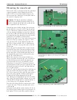
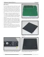
Picture 9. Site of test point M and +5V.
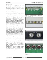
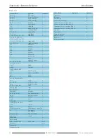
Picture 10. Correct build positioning of IC 2; the site of the in-
dentation (arrowed) is to be paid attention to.
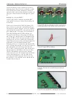
Picture 12. With IC 5 the marker point must be nearest the edge
of the board.
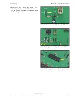
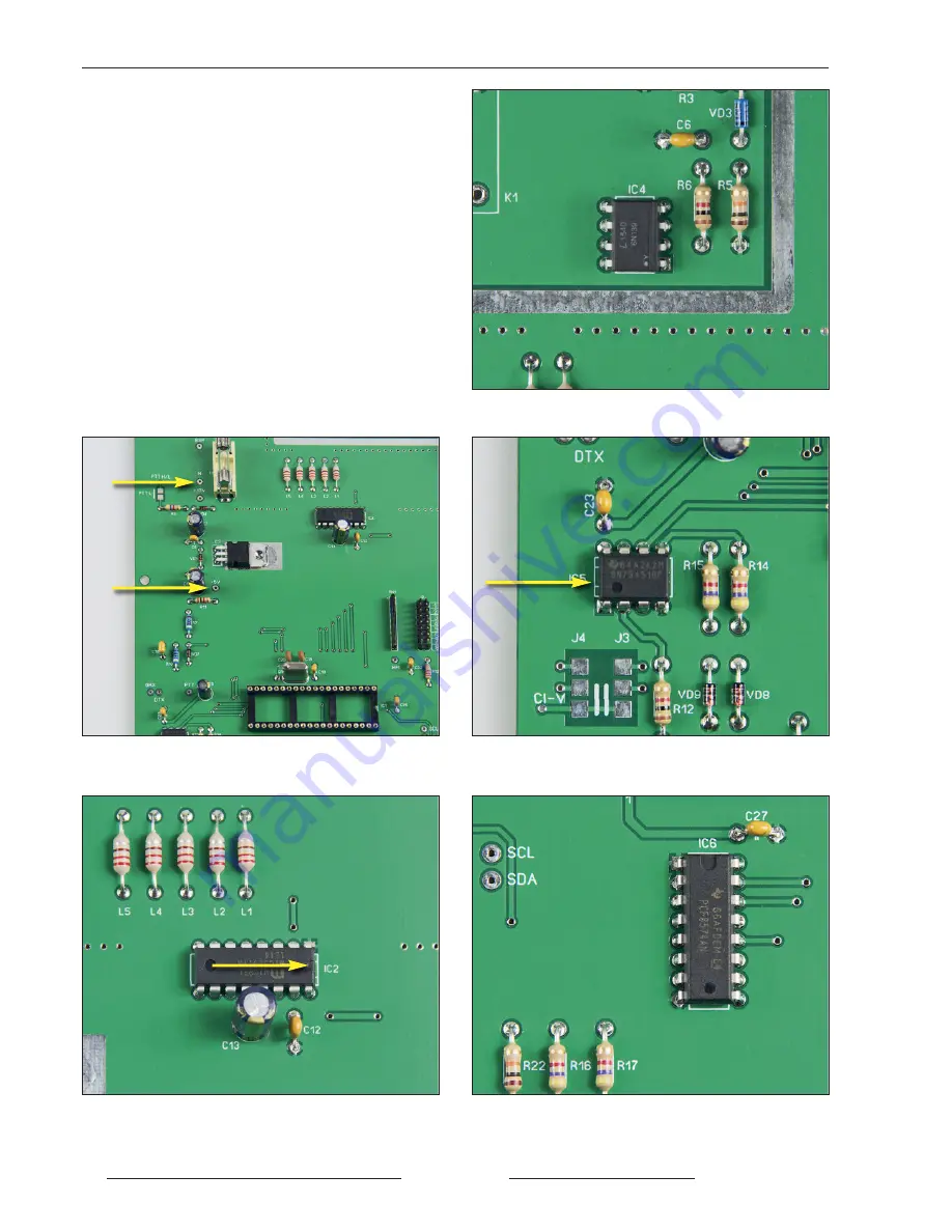
Picture 13. Position of IC 6 after mounting.
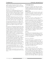
Picture 11. Optical coupling device IC4 soldered in position.
Testing the DC supply
Using the kits accompanying hollow round plug and a twin
core cable, the DC supply should be assembled. The sup-
plied fuse should be placed in its holder and the bench
power supply set to 12V with a current threshold of 0.2A.
The voltage output from the bench supply is now connected
via the DC supply cable to socket 7. With the multimeter at
the +5V test point (picture 9) there should be a reading of
between 4.9V and 5.0V. If not, then it’s the old task of find-
ing out why and correcting the problem before mounting
any more components. As a reference point for calibration
for example, the test point M, near to the fuse, may be used.
When everything is in order the DC supply and board may
be disconnected.
Summary of Contents for BX-7300
Page 20: ...BX 7300 February 2018...


