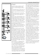
Mounting the IC’s
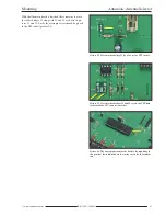
Now follows the mounting of IC2, IC4, IC5 and IC6. It is of
course, crucial they are mounted in the correct orientation.
The position of the indentation must correspond with the di-
agram on the circuit board. The soldered IC’s can be seen in
pictures 10 to 13.
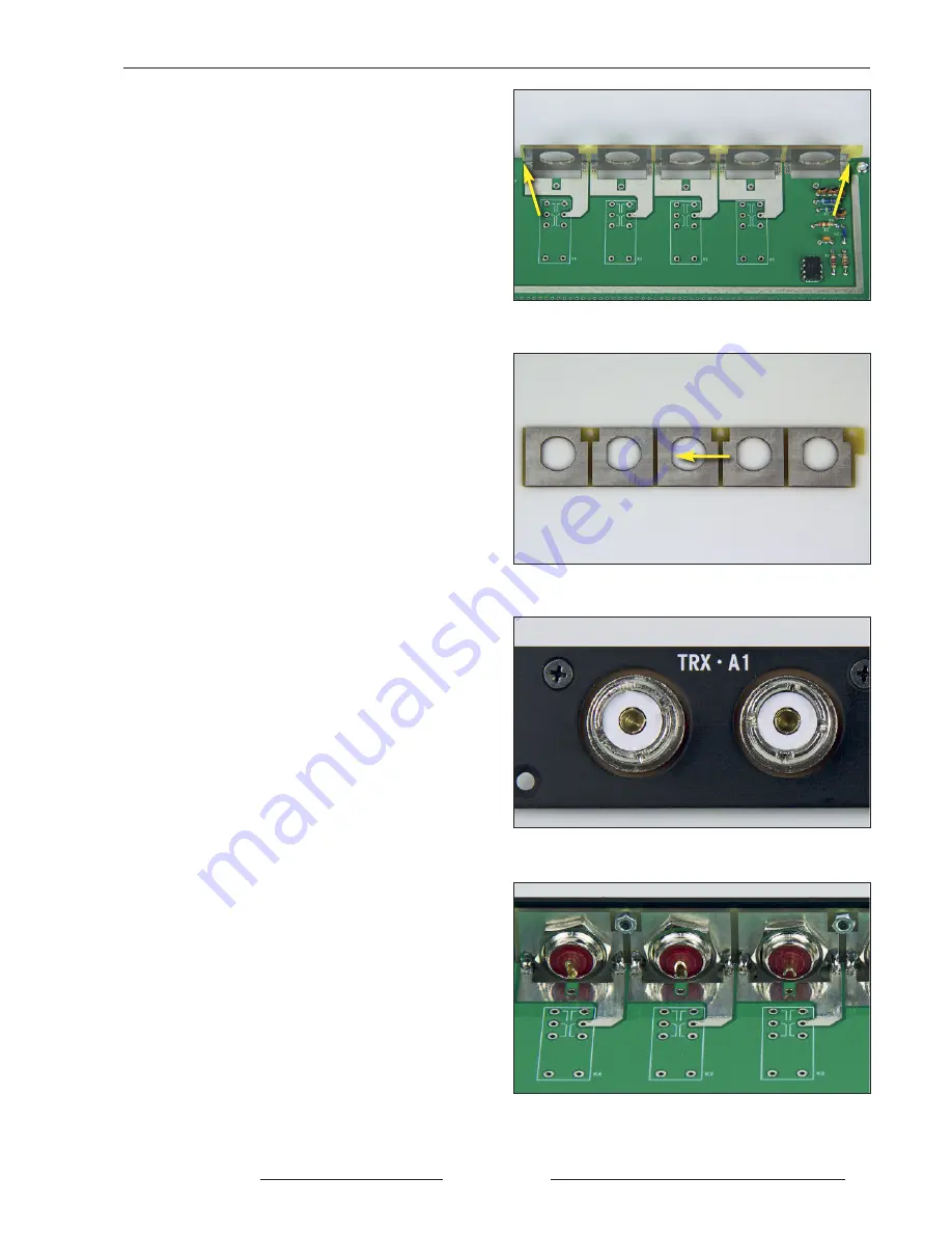
Mounting the socket board
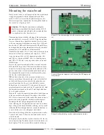
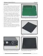
The approximately 1.5mm gap on the back edge of the main
board is so designed that the socket board can be inserted
later. The milled corners may however need a little further
rounding off with a small file and lastly, the socket plate
must sit flush in the main board gap as shown in picture 14.
With the dimensions of the SO239 sockets adhering to as
high a tolerance as possible it can be that a negligible
amount of filing is required afterwards. The aim is that when
the sockets are mounted and sitting in their corresponding
holes there is as little play as possible and that when the are
being screwed and unscrewed they don’t move or twist and
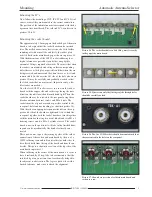
remain stable. In this case the flat side of the hole (shown in
picture 15) may be carefully and gradually worked so that
the fitted socket has no movement. (In practice only a few
file strokes are needed).
Now the five SO239 sockets are set in a row on the socket
board with the copper side and solder tags facing the same
direction, the nuts located and turned hand tight. Then the
socket board may be screwed to the rear panel using three
black countersunk cabinet screws and M3
×
6 nuts. The
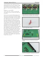
sockets must be aligned as much as possible central to the
rear panel holes and not touching (as shown in picture 16).
With the aid of an appropriate spanner the nuts on the cop-
per coated side of the board are tightened. After which the
rear panel together with the socket board are joined together
with the main board using two metal blocks and two M3
×
4
housing screws and two M3
×
4 cylinder screws. The socket
board is now in the position it will take in the finished hous-
ing and can be mechanically fixed and electrically con-
nected.
There now comes to pass the joining together of the solder
connections of the sockets and main board by the use of a
100W soldering iron and sufficient solder for both sides to
be soldered both from the top of the board and from the un-
derside. This part is shown in a section of the top side of the
main board in picture 17.
When soldering in the corner of the main board it is easier to
have it inclined by 45 deg. Also to bear in mind is that the
insulated leg at any one time is not accidentally bridged to
the adjacent socket section. The legs are quite wide with a
limited tolerance, make sure to check the alignment.
Mounting
Automatic Antenna Selector
BX-7300 • 180403
© www.funkamateur.de
9
Picture 14. The socket board after a little filing, must fit exactly
in the gap of the main board.
Picture 15. If necessary only the flat edges of the through holes
should be carefully worked.
Picture 16. The five SO 239 sockets should be mounted such that
they are centred in the holes on the rear panel.
Picture 17. Shown here a section of soldered main board and
sockets in a row.
Summary of Contents for BX-7300
Page 20: ...BX 7300 February 2018...

