background image

Mounting modules in the elmeg hybird 300

Do not extract or insert modules during operation!

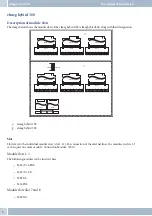
Three different module types and their corresponding module slots have been designed for the elmeg hybird 300 (see
page 8).

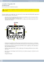
• With the elmeg hybird 300‘s cover removed, you’ll find the module slots 1-3 at the top of the elmeg hybird

300

• Module slots 7-8 are located under the module slot 1 cover. To open cover, see instructions on page 12.

• Module slots 11-12 are located under the module slot 1 cover. To open cover, see instructions on page 12.

They may be electrostatically charged. Before opening the elmeg hybird 300, you must discharge yourself
by touching an earthed conductive object (e.g. water pipe).

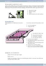
Mount modules for module slots 1-3

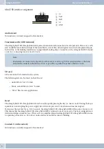
The image shows the example of module slot 3.

1

Module for slot 3.

2

Lateral guide for modules.

3

Module connection in the elmeg hybird
300 housing.

4

Connection Module (in the example

»

MC

CL

«

(see page 8).

5

Plug connection between module
Connection Module.

6

Fixation screws of the “Connection
Module” in the earth bar.

• Place module on lateral guide 2.

• Push in the direction of the arrow into module plug socket3.

»

Connection Module

«

(see page 8) 4 push in the direction of the arrow into the connector of module 5.

• Screw module onto 6 earth bar.

Module 

»

Connection Module

«

 must always be screwed onto the elmeg hybird 300‘s earth bar.

Mounting modules in the elmeg hybird 300

Assembly of elmeg hybird 300

11

Modul
Header RJ45

FSM2

FSM1

FSM3

FSM4

FSM5

FSM6

FSM7

FSM8

2

3

2

2

2

1

5

6

6

4

Summary of Contents for elmeg hybrid 300

Page 1: ......

Page 2: ...om GEMA GermanSociety for MusicalPer formance and Mechanical Reproduction Rights is not required This has been confirmed by GEMA with the follo wingapprovalcertification Theapprovalcertificationcanbev...

Page 3: ...in out 5 Functional earth GND terminal 5 SD card 5 Reset 5 Contacts switch contacts 5 Option 6 ETH1 ETH5 6 LED elmeg hybird 300 6 Status LED rack mounted version elmeg hybird 600 6 Display of LED 1 L...

Page 4: ...4 Technical data Upn interfaces 24 Interface assignment M 4 S U 4U 24 M 4 S U 6 FXS 26 Switch for the terminators 26 Technical data S0 interfaces 27 Technical data Upn interfaces 27 Technical data ana...

Page 5: ...on module FSM 38 Module connections 39 Connection of analogue FXS terminals 39 International 39 System technical data 40 ISDN connections 40 Upn connections 40 Analogue interfaces 40 USB interface 41...

Page 6: ...ences Directsunlight Heatsources e g heatingelements Electronicdevices e g audioequipment office equipmentormicrowaves Penetrationofhumidityorliquids Corrosiveliquidsorvapours Heavydust Onlyopenthosea...

Page 7: ...mmendinstallationofsurgeprotectionforthesystem toguardagainsttheovervoltagethatmay occurduringthunderstorms Consultyourelectricianaboutthis Radio devices e g DECT Bluetooth WLAN Undercertaincircumstan...

Page 8: ...t 7 and 8 M4FXO elmeg hybird 300 Description of module slots 3 Slot 8 Slot 7 Slot 11 Slot 12 Slot 1 Slot 2 Port Slot 3 1 2 3 4 5 6 7 8 1 2 3 4 5 6 7 8 1 2 3 4 5 6 7 8 Port Port 1 2 3 4 1 2 3 4 1 2 3 4...

Page 9: ...232 interface 1 and 2 Theserial1interfaceisdesignedforconnectingalaptop aPCwith serialinterfaceforconsoleapplications Theserial2interfaceisdesignedforconnectingaprinterwith serialinterfaceforhotelapp...

Page 10: ...rds cannot be formatted in the system The following data can be stored on the SD card Audiofilesin wave format Music on holdfilesin wave format Wave filesforvoiceapplications Reset Theelmeghybird300 e...

Page 11: ...ation using a serial connection via the Serial 1 interface Note LED functions ETH1 ETH5 are located on page 31 LED elmeg hybird 300 LED s of the elmeg hybird 300 are located on the upper right corner...

Page 12: ...ormessageif e g theSIPproviderisnotregistered ortheclientisnotdetectedattheUSBhost Theelmeghybird300isinitialised Whenswitchingtooperatingvoltage theLEDblinksuntiltheelmeghybird300isoperative Operatin...

Page 13: ...nserted module Module slot 12 Functional earth strip It is linked with the system GND terminal Functional earth connecting screw This bar links the functional earth strip with the functional earth str...

Page 14: ...rheatsources e g heatingelements orindamprooms Ambienttemperaturemustre mainbetween5 Cand40 C Borehole spacingguidelinesforwallmountingareindicatedatthebackofthesystem 4 Inselectingan installationsite...

Page 15: ...ntenance areas Unauthorised opening of the device may be dangerous to the user Hangthesystemfromabovewithrearmounts1and2intothescrewheads Next checkthesystemforlevelhorizon tal mounting mark lower bor...

Page 16: ...ctive object e g water pipe Mount modules for module slots 1 3 The image shows the example of module slot 3 1 Module for slot 3 2 Lateral guide for modules 3 Module connection in the elmeg hybird 300...

Page 17: ...r for module slot 1 2 elmeg hybird 300 3 Functional earth strip of cover 4 elmeg hybird 300 earth bar 5 Lateral guide for modules 6 Arrows for open direction 7 Catch for cover attachment 8 Detachable...

Page 18: ...ar of the elmeg hybird 300 Only this will create a continuous functional earth connection Remove detachable cover for clamp connector 9 and RJ45 connector 8 The desired covers are easily removed Next...

Page 19: ...on page Module slot 12 This module is mounted on the base module as described on page 12 Base module Module power supply 1 always present Module power supply 2 only in connection with modules on slot...

Page 20: ...tedviapowersupply1 leftslot ThesecondfancanbeconnectedtoFAN2orFAN3 Bothconnectionareswitched parallel and are operated via power supply 2 right slot Note With only mains unit 1 present only fan 1 is i...

Page 21: ...h connection should be as short as possible as ground loops can otherwise ensue Caution All areas which can only be opened with tools are maintenance areas Unauthorised opening of the device may be da...

Page 22: ...moduleplugsocket2intheelmeghybird 300basicmodule Screwthemoduleintothegroundbus3 The module must always be screwed into the elmeg hybird 300 ground bus Mounting modules in mounting frame elmeg hybird...

Page 23: ...s into the module To remove the module push both latches outwards at the same time The module moves into the position shown in the figure It can then be pulled against the direction indi cated A 1 Plu...

Page 24: ...Mounting modules Mounting modules in mounting frame elmeg hybird 600 19...

Page 25: ...es see page 34 The module does not have LED s The image displays module MC CL with removed connecting terminals Module connection RJ45 MC RJ45 The image shows module MC RJ45 Thesocketsdesignatedas FSM...

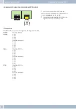
Page 26: ...2 4 a1 5 b1 6 b2 Connections You ll find the connection description in the respective module S0 TE S0 NT Module MCCL 1 a1 2 b1 3 a2 4 b2 Module MCRJ45 3 a2 4 a1 5 b1 6 b2 Upn Module MCCL 1 a1 2 b1 3 n...

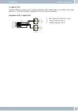
Page 27: ...RJ45 connectors to an RJ45 socket of mod ulesM 4 S U 6 FXS and M 16 FXS Adapter and connection cable are unshielded Assignment of the Y adapter FXS 1 RJ45 connector ratchet lever on top 2 Analogue te...

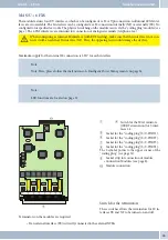
Page 28: ...rface the network provider s NT Here the opposing feeds could damage the devices Note For this please follow the instructions of Intelligent Power Management on page 34 Note LED functions are located...

Page 29: ...Interfaces S0 supply ca 37 5 V Channelstructure B B D Linelengths for a 0 6 mm diameter Shortpassivebus max 120 metres for network line CAT 5 up to 180 metres Technical data Upn interfaces Upnlineleng...

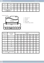
Page 30: ...ce contact number RJ45 socket Connection Connection Feature Port ID 1 2 3 4 5 6 7 8 1 2 3 a2 S S S S 4 a1 S U S U S U S U U U U U 5 b1 S U S U S U S U U U U U 6 b2 S S S S 7 8 Port designation in the...

Page 31: ...2 5W for each interface Note Note Here please follow the instructions of Intelligent Power Management on page 34 Note LED functions are located on page 31 1 4 Switch for the S0 terminators 100R Termi...

Page 32: ...up to 180 metres Technical data Upn interfaces Upnlinelengths 0 6mm Wirediameter 1 000 metres Maximumsupply 2 5 W Technical data analogue interfaces FXS Supply symmetrical 18 mA on 200 600 Ohm Max lin...

Page 33: ...FXS7 FXS8 2 b1 S U S U S U S U FXS5 FSX6 FXS7 FXS8 3 a2 S S S S FXS9 FXS10 4 b2 S S S S FXS9 FXS10 Port designation in the Configuration 1 2 3 4 5 9 6 10 7 8 Module MC RJ45 1 M 4 S U 6 FXS 2 MC RJ45...

Page 34: ...1 2 3 4 5 6 7 8 1 2 3 a2 S S S S FXS9 FXS10 4 a1 S U S U S U S U FXS5 FXS6 FXS7 FXS8 5 b1 S U S U S U S U FXS5 FXS6 FXS7 FXS8 6 b2 S S S S FXS9 FXS10 7 8 Port designation in the Configuration 1 2 3 4...

Page 35: ...connected to the M 8 FXS modules 16analogueterminalscanbeconnectedtothe M16FXS modules Note LED functions are located on page 31 1 Module connection 2 Socket strip for connection of module Connection...

Page 36: ...4 The connecting terminal designation is lo cated under the terminals 5 Connecting terminal number Connection terminal number Connection termi nal designation Port ID 1 2 3 4 5 6 7 8 1 a1 FXS1 FXS2 F...

Page 37: ...S2 FXS3 FXS4 FXS5 FXS6 FXS7 FXS8 5 b1 FXS1 FXS2 FXS3 FXS4 FXS5 FXS6 FXS7 FXS8 6 b2 FXS9 FXS10 FXS11 FXS12 FXS13 FXS14 FXS15 FXS16 7 8 Port designation in the Configuration 1 9 2 10 3 11 4 12 5 13 6 14...

Page 38: ...Flashes Green Off LED functions ETH1 ETH5 1Gbit LED Bezeichnung LED colour Function Status Display LED designation Yellow LAN Off Green 1Gbit Ein Yellow LAN Off Green data traffic Flashes LED function...

Page 39: ...ernally to connec tion of S0 terminals 6 No function production designations for the module The following designations are located on side 1 of the coding plug Upn Thecorrespondingoutputonthe Connecti...

Page 40: ...ue terminals is done in line with the configuration tariff information is transmitted to S0 terminals in the currency amount Thedial endmonitoringcanbeconfigured The time for monitoring the dial end s...

Page 41: ...elmeghybird300 After disconnection of the power supply and removal of the two knurled screws from the elmeg hybird 600 this module may be extracted and replaced If one or more modules 4 6 are present...

Page 42: ...ins voltage 7 Connecting plug for internal power supply 8 Knurled screws for module fixation 9 Screws TORX to attach mounting frame assembly Intelligent power management Thesystemfeatures intelligentp...

Page 43: ...is symmetrical in structure It can be inserted in any direction TheFSMisaone timefuse meaningthatonceamodulehasbeenremoved itmustbereplacedwithanewmodule Ifasurgeprotectionmoduleisactuatedbyanovervolt...

Page 44: ...d300 however canonlybe used via the flash function of the terminal This flash function in turn is only available in the multi frequency dial ling process Analogue terminals feature a 2 wire connection...

Page 45: ...nnection ISDNinterfaces Supply ca 37 5 V Channelstructure B B D ISDNlinelengthsfor 0 6mmwirediameter Shortpassivebus max 120 metres for network line CAT 5 up to 180 metres Upn connections UPnlinelengt...

Page 46: ...ad 24 FXS switched on Fuse primary 630 mA Safetyclass II Lengthofnetwork connectingcable 2 pole ca 2 metres euro flat conforming to DIN VDE 620 Systemdimensions 500 x 370 x 75 mm Systemweight 3 6 kg e...

Page 47: ...ETH5 33 M M 16 FXS 30 32 M 4 S U 6 FXS 26 29 M 4 S U 4U 23 25 M 8 FXS 30 32 Mains connection 1 Mini USB 5 Module connection modules connection modules Std 28 31 32 connecting terminals 21 Module slots...

Page 48: ...Waste disposal B Wireless devices 2 Y Y Adapter FXS 22 Index 43...

Page 49: ...Index 44...

Page 50: ...cations GmbH S dwestpark 94 D 90449 N rnberg For information on support and service offerings please visit our Website at www Funkwerk ec com where you will find a Service Support area Subject to modi...

Reviews: