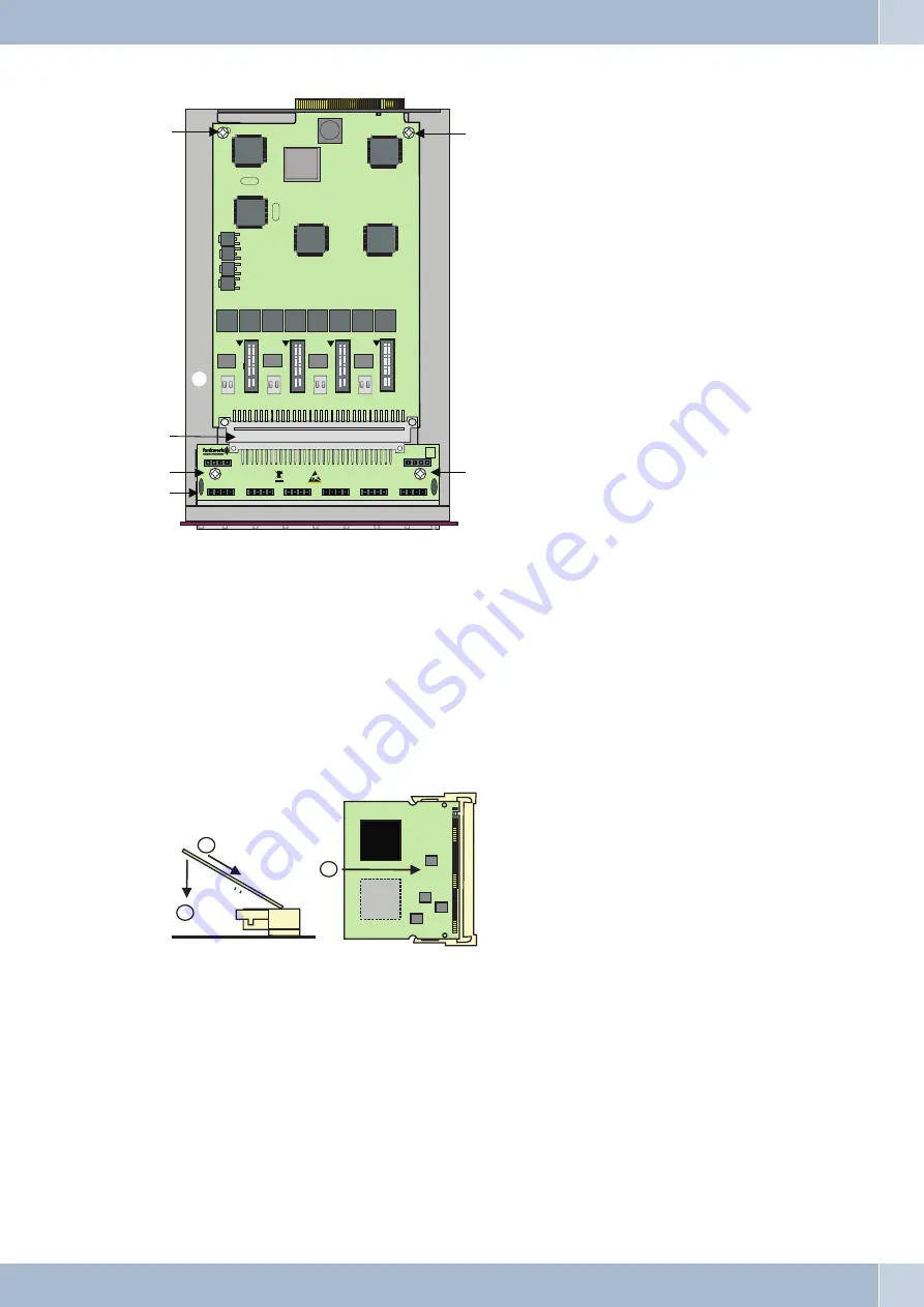
1
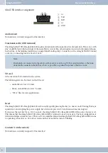
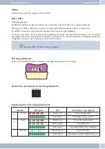
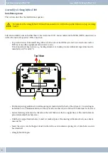
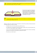
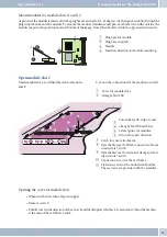
Mounting frame.
2
MC RJ45.
3
4 Fixation screws (scope of supply).
4
Module (example shown M 4 S/U+4 U).
5
Terminal connectors, modules
RJ45 / M 4 S/U+4 U.
Mounting modules for module slots 11-12
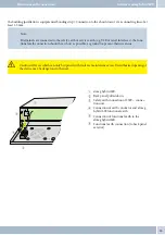
The module is inserted as displayed in the image at an angle of about 45 degrees into the plug-in base (A) and is then
pressed down (B) until the plug latches into the module. To remove the module, push both latches outwards at the
same time. The module moves into the position shown in the figure. It can then be pulled against the direction indi-
cated (A).
1
Plug-in base for module.
2
Plug-in base for module.
3
Latch on the plug-in base.
4
Module.
5
Direction of insertion when installing the
module.
Mounting modules in mounting frame (elmeg hybird 600)
Mounting modules
18
1
2
3
4
A
B
A
Connection Module RJ45
FSM2
FSM1
FSM3
FSM4
FSM5
FSM6
FSM7
FSM8
Sieckmann
ON
1
2
ON
1
2
ON
1
2
ON
1
2
3
4
1
2
3
3
3
5


