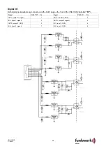
29
VNS 102V2
11/2009
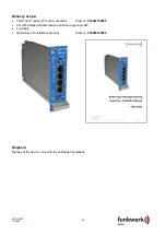
Accessories for the VNS 102V2
19" sub-rack, compl. wired incl. mains cable and 2 dummy boards
Order no. 943525150100
Transformer module TM11
Order no. 943435120300
Dummy boards (7 TE blue)
Order no. 943525180700
Set of cables
Order no. 943525160100
Mounting kit connection unit
Order no. 943522190500
Installation kit AK 187
Order no. 943525150500
CD with Active X (software for displaying video images on the PC monitor)
Order no. 943526110100
Mounting kit cable/air channel 1 HU
Order no. 943525190100
Mounting kit 1 HU cabinet fan
Order no. xxxxxxxxxxxx
Mounting kit cable/air channel 2 HU (cable/air channel-VAS)
Order no. 941714180100
Commissioning/configuration
The VNS 102V2 may only be operated with a suitable power supply unit (9.5 V DC up to 32 V DC; e.g. TM11).
All adjustments during commissioning and servicing are exclusively performed via the control interface and/or a
web browser while the device is closed. The device may only be opened in the factory by trained and authorised
personnel to prevent long-term damage and failure of the cooling system!
With the further configuration steps, we assume that the VNS 102V2 is in
delivery status.
Delivery status:
You can set the delivery status with dip switch 4 and then turning on the voltage supply of the VNS 102V2.
Once the VNS 102V2 has started up, you have to return dip switch 4 to its initial position. Otherwise the delivery
status would be set each time you start up the device.
Required accessories for initial commissioning/configuration
•
Crossed LAN cable (crossover) to the PC (or HUB + 3 LAN cable)
•
Suitable power supply
•
Video
source
•
Monitor
•
Video
cable
Commissioning and configuring the VNS 102V2
Notice
The following configuration allows the transmission of 2 different video signals via LAN from a VNS 102V2
encoder to a VNS 102V2 decoder. Here the video quality is 2CIF with 2Mbit/s bandwidth each. Here, the signal
on video 1 from the encoder is transmitted to video 2 of the decoder and video 2 from the encoder to video 1 of
the decoder. Please only adjust the parameters in the following description. If you deviate from this description,
we cannot guarantee the functioning of the device. Please also note that the screenshots further down partially
depend on the version of your operating system and may therefore deviate.
Setting the IP address of the encoder
•
Connect the LAN port of the VNS 102V2 with the ethernet port of a PC via a crossover-cable (available in
computer stores) with crossed send/receive lines. (You can also establish the connection between
PC
"
VNS 102V2 with non-crossed standard LAN cables by interconnecting a hub/switch.) In this context,
please make sure that the network admits these 2 x 2Mbit/s with enough reserve. Otherwise you will no
longer be able to access the web server during activated transmission.
•
Now turn the VNS 102V2 on (e.g. by connecting a suitable power supply unit).
•
Establish the connection PC/VNS 102V2 with an Internet browser installed on the PC.
•
Before you will be able to change the IP address of the VNS 102V2, you have to establish a connection via
the Internet browser with the VNS 102V2 using the current IP address of the VNS 102V2. With newer
devices, this is the default IP address
192.168.128.2
, subnet mask
255.255.255.0
. If you do not know the IP
address of the VNS 102V2, you can set the VNS 102V2 to the default address at any time as described in
Summary of Contents for plettac VNS 102V2
Page 19: ......


