9
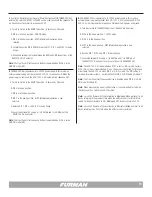
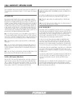
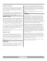
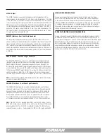
The Multi-Function DIP Switch
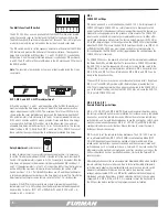
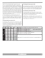
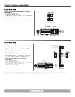
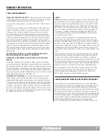
The ASD-120 2.0 has a seven-position Multi-Function DIP switch array located
under the security cover on the front panel to the left of the bypass DIP switch.
The Multi-Function DIP switches are designated 1 through 7 from left to right and
a label for programming can be found on the inside of security cover plate.
This DIP switch is used to set the sequence delay time, active state of the FORCE
OFF feature, and program the behavior of the remote interface. The sequence
delay time is controlled by DIP positions 1, 2, and 3, FORCE OFF is controlled by
DIP position 4, and the remote interface behavior is controlled by DIP positions 5,
6 and 7. The DIP switch settings are ON when in the UP position and OFF when in
the DOWN position.
Note:
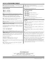
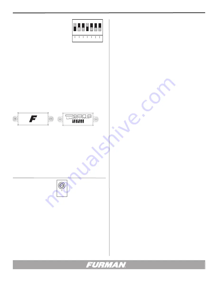
The function of each switch is shown on a label located inside the F logo
cover plate.
ON
DIP SETTINGS
DLY
ADJ
1 2 3 4 5 6 7
ALWAYS ON
ALWAYS OFF
S
E
Q
SET TO
MIDDLE
POSITION
ON
DIP SETTINGS
DLY
ADJ
1 2 3 4 5 6 7
ALWAYS ON
ALWAYS OFF
S
E
Q
SET TO
MIDDLE
POSITION
DIP 4,
FORCE OFF Settings
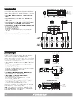
DIP Switch position 4 is used to define how the ASD-120 2.0 will implement its
FORCE OFF feature. FORCE OFF is a safety feature that is designed to cut AC
power to all outlets instantaneously. Many municipalities require this feature as a
means of disabling equipment in the presence of fire or alarm. The FORCE OFF
inputs can be used with a momentary or maintained dry contact in either a Nor-
mally Open or Normally Closed state. The factory default position is DIP 4 ON or
UP, or (NO) Normally Open. In this configuration, the FORCE OFF will be triggered
when the FORCE OFF pins are shorted. If DIP Switch position #4 is on (DIP 4 OFF
or DOWN) the FORCE OFF pins must remain shorted for normal operation. In
this configuration, the FORCE OFF will be triggered when the short between the
FORCE OFF pins is removed.
If a FORCE OFF occurs, the power to all outputs will be immediately disabled and
the Delay Bank LEDs will blink together. To recover from a FORCE OFF condition,
the ASD-120 2.0 must be sequenced off locally, by turning the key swich to the
OFF position. Once reset, normal operations will resume. DIP 4 has priority over
DIP 5, DIP 6, and DIP 7 settings. Information on DIP 5, DIP 6, and DIP 7 can be
found in the following section.
The use of DIP 4 may or may not be a consideration for every install. By default,
DIP 4 is set to the ON (UP) position or (NO) Normally Open; meaning that the
ASD-120 will operate normally with an open circuit applied to the FORCE OFF in-
put. In this default setting, shorting the FORCE OFF pins will cause the ASD-120
2.0 to go into FORCE OFF mode.
DIP 1, DIP 2, and DIP 3: DIP Time Adjustment
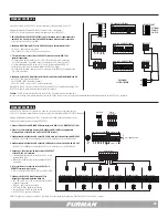
DIP switch positions 1, 2 and 3 and the position of the DLY ADJ (Delay Adjust-
ment) pot control the time delay interval or “dwell time” between consecutive
stages when sequencing ON or OFF. The maximum time for each DIP switch is
shown inside the cover plate label and represents the delay time when the DLY
ADJ potentiometer is fully clockwise. DIP 1 adds 1 minute maximum time delay,
DIP 2 adds 2 minutes and DIP 3 adds 4 minutes. Please note these time delays
are cumulative. If all three DIP switches are in the UP position, the maximum
allowable time delay will be 7minutes, i.e. 1min+2min+4min=7min. The factory
default setting is DIP 1 ON or UP, and DIP 2 and 3 are OFF or DOWN. You can set
these switches in any position you like to achieve your preferred time delay.
Delay Adjustment
(potentiometer)
In order to precisely dial in your preferred sequence delay time, it is necessary
to set the Time Delay Adjustment (DLY ADJ) located left of the multi-function DIP
Switch. If this potentiometer is turned to its 100% value (fully clockwise), then the
time delay will be equal to the maximum time delay defined by DIP switches 1, 2,
and 3. If the potentiometer is in the 12 o’clock position (50%), then the time delay
will be 50% of the maximum time delay interval defined by the setting of DIP
Switch positions 1, 2 & 3. If all three DIP switches are off, and the potentiometer
is turned completely counter-clockwise, the time delay is minimal. The Time Delay
Adjustment potentiometer comes factory-set at 50%, the 12 o’clock position.
Example: If the DIP Switches are set to a 6 minute maximum delay and the po-
tentiometer is set to its 50% setting, then the delay interval between sequenced
banks will be 3 minutes. (DIP 1 OFF or DOWN, DIP 2 and DIP 3 ON or UP = 6
minutes) x .50 = 3 minutes.
1M 2M 4M
N.O.
N.C.
1 2 3 4 5 6 7
ON
MOM
MNT
GND
ON
12V ON
12V OFF
DELAY
1M 2M 4M
N.O.
N.C.
1 2 3 4 5 6 7
ON
MOM
MNT
GND
ON
12V ON
12V OFF
DELAY
Front Back
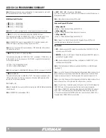
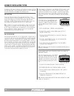
DIP 5, DIP 6 & DIP 7
Remote Mode Trigger Settings
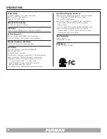
DIP 5 (+12V, ON OFF) and DIP 6 (GND ON) are used in special situations, where
the factory-set remote options are not preferred. For instance, a newly remodeled
location has an existing remote key switch different from a Furman remote key
switch design, and it would be advantageous to use the existing key switch, since
many personnel already have keys. DIP 5 (+12V, ON OFF) and DIP 6 (GND ON)
could possibly address such situations. Please feel free to contact Furman, if
further assistance is necessary.
DIP 7 is used to set the remote switching preference. The ASD-120 2.0 can be
set to a Maintained Mode (DIP 7 OFF or DOWN) or a Momentary Mode (DIP 7
ON or UP) dependent upon the chosen method of remote switching. A Main-
tained switch method stays open until switched, and then remains closed until
switched again (such as toggle switches, e.g. Furman RS-1 key lock switch).The
Momentary switch method is normally open and stays closed only as long as the
button is depressed (such as pushbutton switches, similar to the Furman RS-2
security switch).
Momentary Mode does offer an advantage over Maintained Mode when multiple
remote switching locations are desired. Due to technical flexibility, Momentary
switching easily adapts when implemented with more than one remote switch.
However, maintained switching can be more stable, truly shunting control
voltages when actuated. DIP 5 and DIP 6 offer additional methods of applying
Maintained switching. Regardless of which switching method is chosen, when
changing DIP 4, DIP 5, DIP 6, or DIP 7, it is required to reset the Key Switch to
the OFF position before continuing the programming and installation.


