11
Note:
When programming a new configuration it is recommended to start with
the front panel Key Switch in the OFF position.
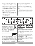
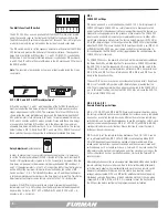
Multi-Function DIP Switch
• DIP 1
1M = 1 Minute Delay
• DIP 2
2M = 2 Minute Delay
• DIP 3
4M = 4 Minute Delay
Note:
DIP 1, 2 and 3 sum together for a total sequence time of 35 minutes.
• DIP 4
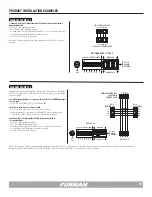
N.O. / N.C. sets the active state of the FORCED OFF input
The factory default setting for FORCED OFF is “ON” or “normally open”. In this
mode, FORCE OFF is triggered when the FORCE OFF pins are shorted.
Note:
If FORCED OFF mode is triggered ASD-120 2.0 will be disabled until
FORCE OFF state is cleared by resetting Key Switch to OFF.
Note:
Force Off overrides the Sequence Bypass DIP Switch and all Delay Bank
LED indicators will flash.
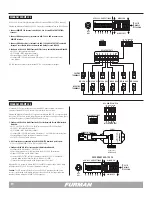
• DIP 5
12VDC ON sets +12V Remote Mode
The factory default setting for 12VDC ON is “OFF” or disabled. If 12VDC ON is set
to ON, the ASD-120 2.0 will sequence ON if 12VDC is applied to the remote pin
on the remote interface.
12V OFF = 12VDC to REM deactivates
12V ON = 12VDC to REM activates
Note:
Factory Default is MAINTAINED ON Mode with DIP 5 set down to 12V OFF.
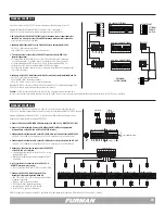
• DIP 6
GROUND ON
The factory default setting for GND ON is “OFF”. If this switch is changed to the
“ON” position, the ASD-120 2.0 will sequence ON when GND is applied to the
remote pin on the remote interface.
REM to GND = ON
Note:
To disable the front panel button completely, the GND ON Maintained Mode
should be used.
Note:
GROUND ON mode overrides DIP 5.
ASD-120 2.0 PROGRAMMING SUMMARY
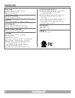
• DIP 7
MOM / MNT - Momentary / Maintained
Sets local mode and remote contact closure preference for either Momentary or
Maintained switches.
Note:
Momentary mode overrides DIP 5 and 6.
Sequence Bypass DIP Switch
• DIP position ON
(A thru F) = Delay Bank and Relay is ALWAYS ON
• DIP position SEQ
(A thru F) = Delay Bank and Relay activates in Sequence
• DIP position OFF
(A thru F) = Delay Bank and Relay is ALWAYS OFF
Note:
Except for a Force Off condition, the Sequence Bypass DIP Switch
overrides any local or remote switch function.
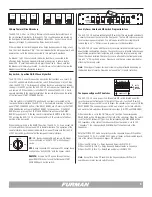
Key Switch
• OFF
= Banks sequence OFF except those configured as “ALWAYS ON” in the
sequence bypass DIP switch.
• REMOTE
= Accepts On/Off signals through the rear panel REMOTE connector
and the Start Sequence button.
• ON
= Banks sequence ON except those configured as “ALWAYS OFF” in the
sequence bypass DIP switch.
Note:
The Start Sequence Button is disabled when DIP 6 is in GND ON mode
(Position UP).
Note:
Loss of AC Power or utility interruption in Maintained Mode will result in all
Banks returning to the previous state when the utility service is restored. Main-
tained On, Banks will return to ON. Maintained OFF, Banks will return to OFF.
Note:
Loss of AC Power or utility interruption in Momentary Mode will result in all
Banks returning to an OFF state when the utility service is restored.
Note:
If switch #4 on the Multi-Function DIP switch is set to OFF (NC Mode) the
FORCE OFF pins on the rear panel must be shorted for normal operation.
In NC Mode, a FORCE OFF condition will be triggered if the FORCE OFF pins are
open circuit. The factory default is ON (NO Mode). In NO Mode, the ASD-120
2.0 functions normally with the FORCE OFF pins open circuit and FORCE OFF is
triggered when FORCE OFF pins are shorted.


