12
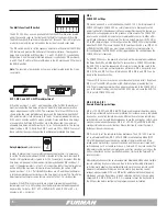
REAR PANEL CONTROL TERMINAL INTERFACE
DELAY OUTPUTS
NC A B C D E F NO
DRY RELAY CONTACTS - RATING 48V / 1 AMP
FORCE OFF
INPUT 120 / 3Ø, 208 / 240 VAC
14400 WATTS – 120 AMPS MAX
20A MAX
DELAY A
20A MAX
DELAY B
20A MAX
DELAY C
20A MAX
DELAY D
20A MAX
DELAY E
20A MAX
DELAY F
FORCE OFF
DELAY OUTPUTS
REMOTE
NC A B C D E F NO
12V STAT REM GND
WARNING! ELECTRIC SHOCK HAZARD. CONNECTION OF A POWER
INPUT CABLE TO THIS DEVICE AND TO A POWER SOURCE MUST BE
DONE BY QUALIFIED PERSONNEL ONLY.
DANGER: MANIPULER SEL ON LES INSTRUCTIONS DU
FABRICANT ET CONFIER LA MAINTENANCE A UN T
ECHNICIEN QUALIFIE
DRY RELAY CONTACTS - RATING 48V / 1 AMP
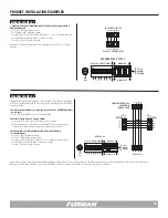
FORCE OFF TERMINAL
The optically isolated FORCE OFF inputs are to be connected to a pair of dry
switch contacts provided by an alarm or emergency kill switch. The ASD-120 2.0
will respond to NC or NO contacts based on the setting of DIP 4. All Delay Banks,
including those configured as “Always On” will be powered off immediately when
FORCE OFF is triggered. When triggered, all the Delay Bank LEDS will blink in
unison while FORCE OFF state is active. The FORCE OFF input is designed with a
12VDC 10mA source for this purpose. To reset FORCE OFF, turn the Key Switch
to the OFF position to clear the condition.
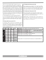
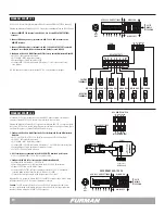
DELAY OUTPUTS TERMINAL
The Delay Outputs are related to the activation
of 6 relay contact. Each DC relay A thru F
is activated when the corresponding Delay
Bank and is switched ON. All outputs share a
common connection at the left or right ends of
this connector that will allow selection between
normally closed (NC) or
normally open (NO).
Note:
The ASD-120 2.0 Remote interface is also compatible with other relay
contact and low voltage DC control interfaces often used by other equipment
brands and manufacturers.
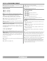
PIN 1 +12VDC (12VDC Voltage Source)
The +12VDC terminal pin is a general purpose, 12VDC voltage source relative to
the GND (#4) pin. It is provided to allow the user to control the operation of the
sequencer by feeding the +12VDC signal back into the REM terminal input; which
is pin #3 on the same barrier strip.
PIN 2 STATUS (Output)
The STAT (status) terminal is an output that may be used to activate an LED to
indicate the status of the ASD-120 2.0. If the STAT terminal is high, the ASD-120
2.0 Delay outlets are either ON, or are in the process of sequencing ON. If the
STAT terminal is low, the ASD-120 2.0 Delay outlets are OFF. To use the STAT
terminal output simply connect an LED between the STAT and GND with the
Cathode (flat) side of the LED oriented toward the GND pin (Pin #4). Do not use a
series current limiting resistor. If the LED does not light when the remote switch
is ON, check the polarity of the LED and reverse the leads if necessary.
• If the LED is OFF, the DELAY outputs are OFF
• If the LED is ON, the DELAY outputs are ON
• If the LED is blinking, the DELAY 1, 2 or 3 outputs are in transition either from
ON to OFF or OFF to ON
PIN 3 REMOTE (Input)
The REM (remote) terminal is provided to allow remotely connected devices to se-
quence the ASD-120 2.0 ON or OFF. The ASD-120 2.0s’ REM terminal has been
designed to work with voltages from 5 to 30VDC. Filtering has been added to this
input to prevent false-triggering. The behavior of the ASD-120 2.0 is controlled
by the combination of the signal presented at the REM terminal input, and the
arrangement of the rear panel DIP switches. Please refer to FRONT PANEL DIP
SWITCH section (page 9) for more details.
REMOTE
12V STAT REM GND
1 2 3 4
Remote Interface
Pin
Label
Description
1
12V
12VDC @250mA General
Purpose Output
2
STAT
Output for driving an
external status LED
3
REM Input for controlling the
sequencer remotely
4
GND Ground (12VDC Power and
Signal Common)
NC
A
B
C
D
E
F
NG
RELAY A
RELAY B
RELAY C
RELAY D
RELAY E
RELAY F
REMOTE INTERFACE
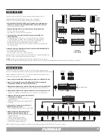
The ASD-120 2.0 has a remote interface which can be used to control the ASD-
120 2.0 remotely using a Furman RS-1 (Maintained) or RS-2 (Momentary) wall
switches. In the most basic, single unit configuration, only two wires and a switch
are required to initiate a remote ON or OFF sequence. The switch may be either
a momentary or maintained-contact type. If a third & fourth wire are available, an
LED “Status Light” can be installed at the remote switching location to indicate
the status of the ASD-120 2.0. The pins on the remote interface are described
below:
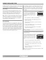
PIN 4 GND (Power)
The GND (ground) terminal operate in unison with Delay A through F. GND can
also be fed back into the REM pin (Pin #3) to activate the sequence when the
ASD-120 2.0 has been configured for GND ON mode. Please note that the GND
terminal on the Remote Interface is not the same as chassis ground and should
never be connected to chassis ground.
The Delays outputs terminal conssist of a se-
ries of six relays, internal to the ASD-120 2.0.
These relays mirror the state of Delay Banks A
through F. The diagram to the right shows how
the relays are wired inside the ASD-120 2.0


