

16
Configuration for Remote Operation
Maintained switches are generally most convenient when there is only one remote
control location. The ASD-120 2.0 is shipped factory-set for Maintained On
operation. The alternate method of controlling the ASD-120 2.0 through the use
of a momentary push button switches can be used when more than one remote
switch location is required.
Note:
The front panel Key Switch must be in the REMOTE position for ASD-120
2.0 to accept commands. Furthermore, an ON or an OFF key position functions
in either DIP 7 Maintained or Momentary mode bypassing all other program
functions except the Bypass Set or a Force Off condition.
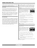
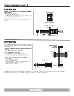
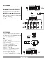
Maintained On - 12V ON/OFF
When the Key Switch is in REMOTE mode, +12V present at the REM input with
respect to GND will initiate an ON or OFF sequence depending on the position
of DIP 5 (12V ON/12V OFF). After the sequence is complete, the output circuits
will remain in the configured state as long as +12V is present. The source of the
+12V can be from the remote interface itself, through remote relay contacts, or
can be supplied by a +12V source from connected equipment. The absence of
12V will cause the ASD-120 2.0 to toggle, and remain in the opposite state.
The ASD-120 2.0 cannot operate in the 12V ON/OFF Maintained Mode when DIP
6 is set to the GND ON mode. The GND ON switch will take priority. In 12V ON/
OFF Maintained Mode, one cannot use the START ON/OFF SEQUENCE button.
If someone does press the button, the ASD-120 2.0, if ON, will start an OFF
sequence that will last until you release the button.
Note:
To disable the front panel button Start Sequence completely, the GND ON
Maintained Mode should be used.
Maintained On - GND ON
A simple connection from the REM terminal to the GND will initiate an ON se-
quence when DIP 6 is in the up position. After the sequence is complete,
the output circuits will remain in the configured state as long as the ground con-
nection to REM is present. Opening this connection initiates the OFF sequence.
When DIP 6 is set for GND ON, the position of DIP 5 12V ON/OFF is ignored.
Note:
The Start Sequence button has no effect when thw ASD-120 2.0 is in
GND ON mode.
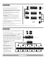
Maintained Off Mode
In the Maintained Off Mode, the ASD-120 2.0 will sequence ON or OFF with the
Key Switch or a remote activation trigger. In this mode the ASD-120 2.0 will
always remain in an OFF state until a connection is present between the REM
and GND terminals or between the 12V and REM terminals.
DIP #7 switch is set in the down position (MNT) for operation in Maintained
Mode. And when utilizing the REM and GND terminals, an ON response can be
programmed by setting DIP switches #5 and #6 accordingly. And when utilizing
the 12V and REM terminals, the same is true. The connection to the REMOTE
interface must exist, whether it be a presence or absence of 12V or open/closed
contacts. This mode is not typically used.
Note:
The Start Sequence Button is disabled when DIP 6 is in GND ON mode
(Position UP).
Momentary Mode
In the Momentary Mode, a momentary switch such as the one located on the
front panel of the ASD-120 2.0, or the Furman RS-2 remote switch panel, can
be used to initiate an ON or OFF sequence. The Momentary Mode is selected
when DIP #7 (MOM/MNT) is in the up (MOM) position and DIP #6 (GND ON) is
in the down position. The position of DIP #5 (12V ON/12V OFF) is ignored. In
Momentary Mode, the ASD-120 2.0 will toggle between ON and OFF sequences
every time a trigger is received from the front panel button or at the REM terminal
with respect to GND. Multiple Furman devices with a REMOTE interface can be
synchronized by connecting the REM and GND terminals together.
When the ASD-120 2.0 has been configured for momentary mode, the REM
connection at the rear panel can act as an input or output depending on which
button is pressed. If the ASD-120 2.0 button has been pushed, the REM
connection provides a +12V output for as long as the button is depressed. Any
connected Furman products with REM and GND terminals will also cycle on or off.
To synchronize all equipment connected together in this way, press the START
SEQUENCE button for at least 6 seconds. The outputs of all connected products
will be shut off. If the connected product is a sequencer, the Sequence OFF will
be triggered. If remotely triggered, the sequence starts on the rising edge of the
signal at the REM terminal.
All Furman products connected in this way must be configured for Momentary
Mode. When first plugged in (or after power is lost and reapplied for any reason),
the ASD-120 2.0 outputs will remain off until a momentary trigger is received at
the REM input or the START SEQUENCE button is pressed. Pressing the START
SEQUENCE button while an ON or OFF sequence is in progress will result in an
immediate change in direction of the sequence.
Note:
Loss of AC Power in Momentary Mode will result in all Banks returning to
an OFF state when the utility service is restored.


