
22
3 YEAR LIMITED WARRANTY
PLEASE SAVE YOUR SALES RECEIPT!
The receipt is your proof of purchase and
confirms the product was purchased at an authorized Furman dealer. It will need
to be submitted to Furman in order to process any warranty claims.
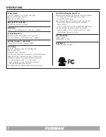
Furman, a brand of Core Brands LLC., warrants its ASD-120 2.0 (the “Product”)
as follows:
Furman warrants to the original purchaser of the product that the product sold
hereunder will be free from defects in material and workmanship for a period
of three years from the date of purchase. If the product does not conform to
this Limited Warranty during the warranty period (as herein above specified),
purchaser shall notify Furman of the claimed defects by calling 800-472-5555
or via email (techsupport@furmansound.com). If the defects are of such type and
nature as to be covered by this warranty, Furman shall authorize purchaser to
return the product to Furman. Warranty claims MUST be accompanied by a copy
of the original purchase invoice or receipt showing the purchase date. Shipping
charges to Furman must be prepaid by the purchaser of the product. Furman
shall, at its own expense, furnish a replacement product or, at Furman’s option,
repair the defective product. Return shipping charges back to purchaser will be
paid by Furman.
THE FOREGOING IS IN LIEU OF ALL OTHER WARRANTIES, EXPRESS OR
IMPLIED, INCLUDING BUT NOT LIMITED TO THE IMPLIED
WARRANTIES OF MERCHANTABILITY AND FITNESS FOR A PARTICULAR
PURPOSE.
Furman does not warrant against damages or defects arising out of improper
use or abnormal handling of the product, or against defects or damages arising
from improper installation. This warranty shall be cancelable by Furman at its sole
discretion if the product is modified in any way without written authorization from
Furman or Core Brands LLC. This warranty also does not apply to products upon
which repairs have been affected or attempted by persons other than pursuant to
written authorization by Furman or Core Brands LLC.
THIS WARRANTY IS EXCLUSIVE.
The sole and exclusive obligation of Furman
shall be to repair or replace the defective product in the manner and for the
period provided above. Furman shall not have any other obligation with respect
to the products or any part thereof, whether based on contract, tort, strict liability
or otherwise. Under no circumstances, whether based on this Limited Warranty
or otherwise, shall Furman be liable for incidental, special, or consequential dam-
ages. This Limited Warranty states the entire obligation of Furman with respect to
the product. If any part of this Limited Warranty is determined to be void or illegal,
the remainder shall remain in full force and effect.
SERVICE
NOTE:
All equipment being returned for repair must have an RMA (Return Mate-
rials Authorization) number. To receive an RMA number, please contact Furman
Technical Services at techsupport@furmansound.com or call, (800) 472-5555,
between the hours of 6 a.m. and 4 p.m., U.S. Pacific Time. In order to issue an
RMA number, Furman will require the Model and Serial Number of the product,
your name, address, phone number, and a brief description of the problem. An
email address, if available, will be helpful in expediting your RMA. If the unit
is being returned for warranty service, further information may be required to
substantiate the warranty status.
Please be sure that your RMA product is adequately packed and cushioned
against damage in shipment. We suggest that you retain and use the original
packaging to ship RMA materials for servicing. Furman assumes no liability for
damages that occur during shipment. The RMA number should be prominently
displayed on the shipping label or outside of the package. Please enclose a note
with the RMA number, the Serial Number, your name, address, phone number
and a brief description of the problem – failure to do so may delay diagnosis and
repair
Furman Sound and Core Brands LLC. reserve the right to repackage and return
repaired items using packaging materials deemed appropriate and suitable to
for safe transit. Customer supplied materials, such as blankets, bubble wrap,
packaging foam, and the like may be discarded if not suitable for shipment. Addi-
tionally, professional containers such as Road/Flight Cases may be shipped back
separately at the owner’s expense if Furman Technical Services determines that
the Road / Flight Case is unsuitable for the safe return of the RMA Materials.
WARRANTY INFORMATION
CAUTION! WARRANTY LIMITATION FOR INTERNET PURCHASERS
Furman products purchased through the Internet do not carry a valid Product
Warranty unless purchased from an Authorized Furman Internet Dealer and the
original factory serial numbers are intact (they must not have been removed,
defaced or replaced in any way). Purchasing from an Authorized Furman Internet
Dealer insures that the product was intended for consumer use, has passed all
quality inspections and is safe. Buying through auction sites or unauthorized deal-
ers may result in the purchase of salvaged, failed and/or products not intended
for use in the US. In addition, Authorized Furman Internet dealers have demon-
strated sufficient expertise to insure warranty compliant installations.
For a list of Authorized Furman Internet Dealers go to www.furmansound.com
Units under warranty shall be returned free of charge as stated in the Limited
Warranty section of this manual. If you have any questions, please contact
Furman Technical Services between 6 a.m. and 4 p.m., U.S. Pacific Time,
800-472-5555, or via email techsupport@furmansound.com


