
3
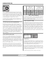
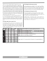
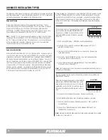
120/208 3 Phase
5 Conductor
3 Conductors at 40A
Loss/ft (W) vs. % Load
120/240 Single Phase
4 Conductor
2 Conductors at 60A
Loss/ft (W) vs. % Load
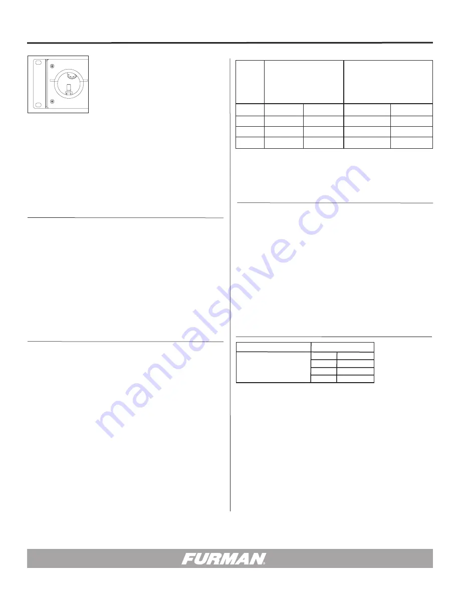
AWG 100% Load 50% Load 100% Load 50% Load
6 3.8 W/ft 0.9 W/ft NA NA
4 2.4 W/ft 0.6 W/ft 3.6 W/ft 0.9 W/ft
2 1.5 W/ft 0.4 W/ft 2.3 W/ft 0.6 W/ft
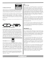
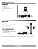
If the equipment is to be portable, a common connection method is to permanent-
ly attach a short cable whip to the Furman and terminate it with a high-current
connector. A long feeder cable with a mating connector would then be prepared
which could easily be disconnected for storage.
3. Prepare and connect the AC supply:
The AC supply cable will be connected to the internal bus bars via terminals that
secure the individual conductors with set screws. These terminals can accept
wires as large as 2 AWG. Strip one end of the cable to expose the wires. When
removing the outer jacket, be careful not to nick or cut into the insulation of the
individual conductors. When stripping the individual conductors, be careful not
to cut through any of the copper strands. All of the individual conductors should
be stripped one-half inch. After threading the cable end through the strain relief
clamp, connect the stripped conductors to the bus bar blocks. Be sure to put
each wire in the lower part of its terminal, so that it is compressed above and be-
low by copper rather than by the set screw itself. Tighten the set screws securely.
Table 1 – Cable Loss Comparison
Prior to use, an appropriately sized power cable must be installed on the ASD-
120 2.0. A qualified electrician should be employed for selection of cabling and
installation. Bus bars for the connection of AC input power are accessible when
the top panel is removed. One safety ground terminal is also provided. The ASD-
120 2.0 is configured for 120/208 three phase power at time of shipment, but a
120/240V single phase source can be supported. Heavily loaded circuits can be
re-distributed between phases to balance the load as necessary.
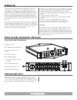
The following instructions are provided as a guide for powering the ASD-120 2.0.
All steps should be performed while the unit is disconnected from power and
before it is installed in an equipment rack.
1. Determine the power source to be used with the ASD-120.
In North America, there are two possibilities: 120/208V three phase, and
120/240V single phase (sometimes called “Single Split”). Three Phase requires
an additional conductor, but it provides better copper utilization. A three phase
source will require five conductors; X (L1), Y (L2), Z (L3), N, and Safety GROUND.
The source must be a “Y” or “Wye” configuration and must include a star point
neutral. A 120/240V single phase source is connected with four conductors;
X (L1), Y (L2), N, and Safety GROUND. If the loads are balanced, the neutral cur-
rent will be zero, but if the load is predominately on one phase, the neutral must
support the entire load current. Since phases are distributed to different circuits
a neutral conductor of the same gauge is the minimum recommendation,
a licensed electrician may recommend a thicker gauge neutral based on other
technical considerations.
2. Select a cable and determine its length.
If the ASD-120 2.0 is installed in a permanent or semi-permanent location, it is
possible to connect it with flexible metal-jacketed conduit. A flexible type SOW
or SOOW supply cable known as a “whip” is recommended for portable use. In
three phase applications, the whip must carry a rating of 40 Amps minimum in
each of three out of five conductors; and for a single phase 120/240 source, a 60
Amp rated minimum for load current in two out of four conductors. The minimum
recommended conductor gauge is 6AWG for a 120/208 three phase source and
4AWG for a 120/240 single phase source.
Cable efficiency losses per foot are listed in Table 1. Losses are dramatically
reduced at lower currents since the losses are a function of the square of the
current. A larger cable size should be considered for critical loads that have high
peak currents, such as power amplifiers. Cable lengths can be longer if the load
current is significantly below the rated maximum, and if large transient peaks are
not expected.
4. Load Balancing:
The load should be balanced between phases. As shipped, the load circuits are
evenly divided among the X, Y, and Z bus bars in support of a balanced 120/208V
three phase input. If a 120/240 source is connected to the ASD-120 2.0, the Z
bus bar is not used and the load conductors connected to this bus bar must be
moved to the appropriate X and Y bus bars. (Please see Table 2.)
By default, there are two 12 AWG black conductors connected by Fast-On termi-
nals to each bus bar. The black wires are labeled with a letter (A, B, C, D, E, or F)
corresponding to the circuit to which it is connected. Since the load is applied in
a sequence, the loads should be alternately applied to each phase as determined
by the position of the load phase conductors.
An example of how the loads should be connected is shown in Table 2.
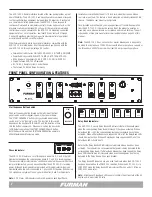
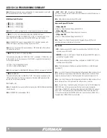
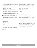
POWER DISTRIBUTION BLOCK
MAX VOLTS: 240 VAC
MAX AMPS: 60A / PHASE
120A TOTAL
TORQUE SPECIFICATIONS
AWG
lb-in (N-m)
2
45 (5.1)
3
50 (5.6)
4 - 6
50 (5.6)
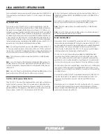
INPUT 120 / 3Ø, 208 / 240 VAC
14400 WATTS – 120 AMPS MAX
20A MAX
DELAY A
20A MAX
DELAY B
20A MAX
DELAY C
20A MAX
DELAY D
20A MAX
DELAY E
20A MAX
DELAY F
FORCE OFF
DELAY OUTPUTS
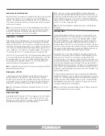
REMOTE
NC A B C D E F NO
12V STAT REM GND
WARNING! ELECTRIC SHOCK HAZARD. CONNECTION OF A POWER
INPUT CABLE TO THIS DEVICE AND TO A POWER SOURCE MUST BE
DONE BY QUALIFIED PERSONNEL ONLY.
DANGER: MANIPULER SEL ON LES INSTRUCTIONS DU
FABRICANT ET CONFIER LA MAINTENANCE A UN T
ECHNICIEN QUALIFIE
DRY RELAY CONTACTS - RATING 48V / 1 AMP
WIRING INSTRUCTIONS