6
The ASD-120 2.0 has a host of features and options that will be highlighted in
this manual.
Here is a quick overview:
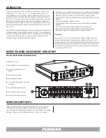
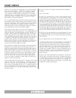
The ASD-120 2.0 can be thought of as an array of six high current relays that op-
erate under the control of a microprocessor. The six relays (referred to as DELAY
A through DELAY F) control the ON/OFF state of the power to six receptacles (also
referred to as DELAY A through DELAY F) located on the rear panel. The ON or
OFF state of each of the six receptacles is indicated by a series of six green status
LEDs on the front panel. There are a series of six circuit breakers located on the
front panel (underneath the status LEDs) that protect the loads connected to each
of the receptacles, DELAY A through DELAY F. Finally, there are a series of six low
power relays that operate in unison with the power switching relays. The contacts
of these low power relays are available on the right side of the rear panel and
allow the user to connect low voltage and low power devices to the ASD-120 2.0.
The ASD-120 2.0 has a rectangular security cover on the front panel. This cover
can be removed to provide access to an array of switches that are used to con-
figure the operation of the ASD-120 2.0. Details of these switches can be found
later in this manual.
The basic operation of the ASD-120 2.0 can be described as follows:
Six individual Delay Banks feature a 120 Volt 20 Ampere AC circuit, and each AC
circuit can be sequenced on or off with a programmable delay at set intervals.
On/Off sequences can be initiated with ASD-120 2.0 front panel switches or a
wired connection to the ASD-120 2.0 rear panel Remote interface. Each Delay
Bank has one NEMA 5-20R duplex provided on the rear panel. In addition, any
Delay Bank can be configured as Always On or Always Off independent from the
sequence. The Delay Banks also have their own independent DC relay terminal
for triggering other devices, including another ASD-120 2.0 or any Furman
sequencing product.
The ASD-120 2.0 should be configured at time of installation. X Y Z Status LED
indicators confirm the input phase of AC power. The configuration DIP switches
are located behind a cover plate in the center of the front panel. A potentiometer
is used to set delay timing intervals. After the ASD-120 2.0 is configured, the
cover plate prevents inadvertent changes and tampering. A locking switch with a
removable key is provided for added security.
PRODUCT OVERVIEW
The ASD-120 2.0 can be used as a stand-alone unit or in combination with other
Furman power distribution devices. The ASD-120 2.0 provides six sequenced
120V, 20A circuits for a total load power of 14.4kW. Higher levels of power
can be achieved by connecting additional Furman sequencers or other power
conditioning products, including additional ASD-120 2.0 units. Furman products
provide a practical means of centralized control over an extensive network of
power distribution and conditioning equipment.
As most sound reinforcement professionals know, AC power sequencing is neces-
sary because the majority of equipment damage occurs when devices are either
powered up or powered down. In addition, power sequencing is needed whenever
various kinds of equipment must be powered up or down in discrete groups,
rather than simultaneously. Power sequencing allows equipment to be powered
up and powered down in an orderly and time-delayed sequence.
In professional audio, power sequencing is used to prevent speaker “pop” in
speaker cabinets, enclosures and line arrays. The “pop” is generated when audio
sources are switched on or off while an amplifier is still “live” or energized. The
activation of source (signal processing) equipment often creates a small spike of
transient voltage. When this voltage is amplified by the amplifiers, the resulting
“pop” can be deafening and can easily damage speaker voice-coils. The reverse
or “power down” of signal processing equipment can create a similar effect as
during power down many devices emit uncontrolled transients. Power down
transients can result in speaker “pop” and damage speaker components as well.
Because AC power sequencing prevents this universally unwanted and often
costly circumstance, AC power sequencing is prudent.
Power sequencing has the added benefit of preventing nuisance breaker trips by
offsetting the in-rush current demands of connected equipment over time. It is
not difficult to imagine the extreme current demand that would be placed upon a
breaker if all connected loads were to be activated at the same time. Power se-
quencing allows equipment to be sequenced on in discrete stages - which allows
each device to power up and current demands to stabilize individually. Although
each device will undergo its own in-rush current at power up, because these
events occur over time, the stress placed upon the breaker is greatly reduced.
For this reason, AC power sequencing is a reliable strategy for protecting event
productions and electrical infrastructure.
Years ago Furman introduced the original ASD-120, along with a full line of power
sequencers, to address the concerns outlined above. Furman power sequencing
products have been used by professional audio experts in a multitude of applica-
tions for decades. When conceiving the ASD-120 2.0, we listened intently to the
voice of our customers and industry experts. We appreciate all of the feedback
and believe that the ASD-120 2.0 delivers the power switching needs and wishes
of all of our customers.


