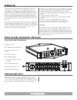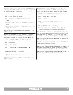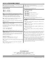
20 Amp Thermal Circuit Breakers
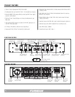
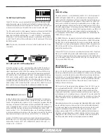
The ASD-120 2.0 has six, 20 Amp thermal circuit breakers that protect each of
the six individual Delay Banks (A through F). The circuit breakers are located on
the front panel immediately below the Bank Status LEDs. Each of the six circuit
breakers (A through F) correspond to a Delay Bank (A through F)
If the combined current level plugged into a Delay Bank exceeds 20 Amps at any
time, the circuit breaker will “trip”, the circuit breaker button will pop outward, and
power will be cut to the devices connected to that particular Delay Bank.
If a breaker “trips” the user should review the load that is connected to the
offending Delay Bank and make adjustments as necessary to reduce load to
below 20A. To reset the breaker simply press the button in. Please note that
the breakers are thermally activated. It is best to wait a few minutes to allow the
breaker to cool before attempting to reset it.
8
ON
DIP SETTINGS
DLY
ADJ
1 2 3 4 5 6 7
ALWAYS ON
ALWAYS OFF
S
E
Q
SET TO
MIDDLE
POSITION
REMOTE
OFF ON
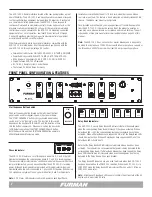
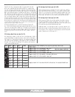
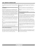
Key Switch - 3 position ON/OFF Security Switch
The ASD-120 2.0 has a three position key switch that functions as a Local ON
Local OFF, and Remote interface selection switch. When the key is in the ON po-
sition, the ASD-120 2.0 will sequence all Delay Banks on and remain on. When
the key is in the OFF position, the ASD-120 2.0 will sequence all Delay Banks OFF
and remain off. When the key is in the REMOTE position the ASD-120 2.0 will
operate according to the signal presented at the remote interface and the action
of the front panel START SEQUENCE button.
If the key switch is in the REMOTE position and no signal is presented on the
rear panel Remote interface, the ASD-120 2.0 will operate according to the front
panel START SEQUENCE button. If the DELAY BANKS are off, pressing the START
SEQUENCE button will cause the DELAY BANKS to sequence on. If the DELAY
BANKS are on, pressing the START SEQUENCE button will cause the DELAY
BANKS to squence off. If the key switch is rotated from REMOTE to the ON or
OFF position, the ASD-120 2.0 will sequence ON or OFF according to the final
position of the key switch.
When the key switch is in the REMOTE position, the ASD-120 2.0 can accept on/
off commands from the rear panel 4-Pin Remote interface. The operation of the
remote interface is explained elsewhere in this manual. Please note that the ON
or OFF key switch positions defeat the rear panel remote interface.
ON
: ON: Banks sequence ON and remain ON except
those configured as “ALWAYS OFF” with the bypass
switch.
OFF
: Banks sequence OFF and remain OFF except those
configured as “ALWAYS ON” with the bypass switch.
REMOTE:
Accepts On/Off signals through the rear
panel REMOTE connector and the front panel START
SEQUENCE push-button switch.
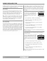
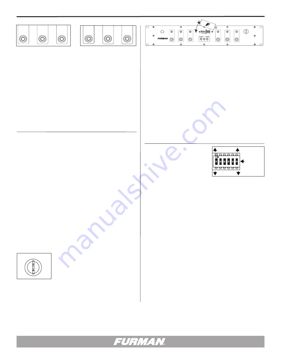
Security Cover Shield and DIP Switch Program Interface
The ASD-120 2.0 had two configuration DIP switches that are located underneath
a security cover near the center of the front panel. The two DIP switches are used
to set various sequencer options. You will need a small Philips screwdriver to
remove two 6-32
3
/
8
” Philips screws to gain access to these switches.
The ASD-120 2.0 comes with the security cover pre-installed to protect against
unauthorized configuration changes. The security cover is intended to discourage
unauthorized personnel from tampering with or adjusting set programming once
the unit has been installed. The security cover is attached to the front panel using
two 6-32
3
/
8
” Philips head screws. Please use only the two screws provided for
attaching the security cover.
Note:
Other types of tamper-resistant screws may be preferable depending on
the desired level of security. Please do not exeed the
3
/
8
” length restriction.
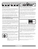
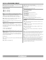
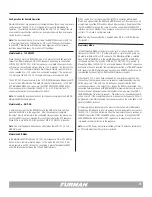
The Sequence Bypass DIP Switches
The ASD-120 2.0 has a six-position, three-state DIP switch located under the
security cover on the front panel to the right of the multi – function DIP switch.
The sequence bypass switch is used to bypass the sequencing on any or all of the
DELAY BANKS. The sequence bypass switch is an array of six tri-state switches,
and each tri-state switch has three possible positions (ON. OFF, and SEQUENCE).
When the switch is set to the ON (“Always On”) position, the corresponding
DELAY BANK will be ON regardless of the state of the sequencer. When the switch
is set to the OFF (Always Off”) position, the corresponding DELAY BANK will be
OFF regardless of the state of the sequencer. When the switch is set to SEQ
(“Sequence”), the corresponding DELAY BANK will follow the state of the
sequencer.
Note that FORCE OFF mode has priority over the sequence bypass DIP switches.
When the ASD-120 2.0 is in FORCE OFF mode, all banks will be disabled regard-
less of the state of the sequence bypass DIP switches.
DIP position ON (A thru F) = Delay Bank and Relay is ALWAYS ON
DIP position SEQ (A thru F) = Delay Bank and Relay activates in Sequence
DIP position OFF (A thru F) = Delay Bank and Relay is ALWAYS OFF
Note:
Except for a Force Off condition, the Sequence Bypass DIP Switch
overrides any local or remote switch function.
START
SEQUENCE
REMOTE
DLY
ADJ
DELAY A DELAY B
DELAY C
PHASE
X Y Z
DELAY D DELAY E
DELAY F
OFF ON
1 2 3 4 5 6 7
ASD-120 2.0
120 AMP POWER SEQUENCER
(SEE COVER PLATE)
ALWAYS ON
ALWAYS OFF
S
E
Q
START
SEQUENCE
REMOTE
DLY
ADJ
DELAY A DELAY B
DELAY C
PHASE
X Y Z
DELAY D DELAY E
DELAY F
OFF ON
1 2 3 4 5 6 7
ASD-120 2.0
120 AMP POWER SEQUENCER
(SEE COVER PLATE)
ALWAYS ON
ALWAYS OFF
S
E
Q
START
SEQUENCE
REMOTE
DLY
ADJ
DELAY A DELAY B
DELAY C
PHASE
X Y Z
DELAY D DELAY E
DELAY F
OFF ON
1 2 3 4 5 6 7
ASD-120 2.0
120 AMP POWER SEQUENCER
(SEE COVER PLATE)
ALWAYS ON
ALWAYS OFF
S
E
Q
1M
2M
4M
N.O.
N.C.
1 2 3 4 5 6 7
ON
MOM
MNT
GND
ON
12V ON
12V OFF
DELA
Y


