


ASD-120 SEQUENCED POWER DISTRO
4
Introduction
Congratulations on your purchase of a Furman ASD-120 Sequenced Power
Distro. Please read this manual completely before installing your ASD-120.
Features
●
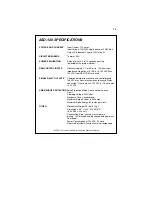
120 amp total load
●
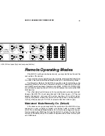
Six 20 amp, 120 volt circuits, each with a STATUS indicator
●
Four buss design accommodates 120/240V single phase, or 208V three
phase power
●
Six 20A duplex outlets on rear panel
●
Outlets are powered up and down in sequence
●
Three position ON/SEQ/OFF switch per circuit allows each circuit to be part of
the power sequencing, or to be switched on/off independently
●
Sequence on/off can be initiated from unit or remotely
using almost any type of control wires
●
Six separate, low level relays provide contact closure (or opening) to control and
sequence other units, such as additional ASD-120’s, Furman PowerPorts,
MiniPorts, PowerLinks and the PS-8R and PS-PRO Power Sequencers
●
Front panel key switch for security
●
Six LEDs on the front panel show status of each circuit
●
STATUS indicators for each incoming phase
●
Basic MOV spike and surge suppression
●
Compact two rack space package
Description
The ASD-120 is an extremely compact, low cost rackmount power distribution
system that is ideal for touring PA systems, touring musical and theatrical acts,
mobile recording facilities, on-location film and video shoots, etc.—any situation
where AC power must be distributed to multiple circuits and a hard-wired, built-in
system is missing, inadequate, or impractical. Use of a Power Distro is cost-effec-
tive, both in terms of the convenience it offers and the elimination of bulky and
expensive parallel feeds and related connectors.
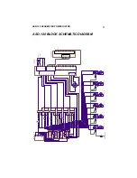
The ASD-120 is a Sequenced Power Distro. It can handle up to 120 amps of
incoming power, distributing it to six 20 amp, 120V circuits. Each circuit has a front
panel STATUS indicator that lights up when it is turned on, and a 20 amp duplex
outlet on the rear panel. The ASD-120 allows you to sequentially power up and
down its six rear panel duplex outlets, each of which is protected by a 20-amp
thermal breaker. The delay interval is user-adjustable via an internal trimpot.
Power sequencing is needed whenever various kinds of equipment must be
powered up or down in groups, rather than all simultaneously. In audio systems,
sequenced powering is often necessary to allow turn-on transients from low level
amplifiers and processors to settle down before any power amps are turned on,
because simultaneous powering would result in a loud, annoying, and potentially


