P S - 8 R - P O W E R C O N D I T I O N E R / S E q u E N C E R
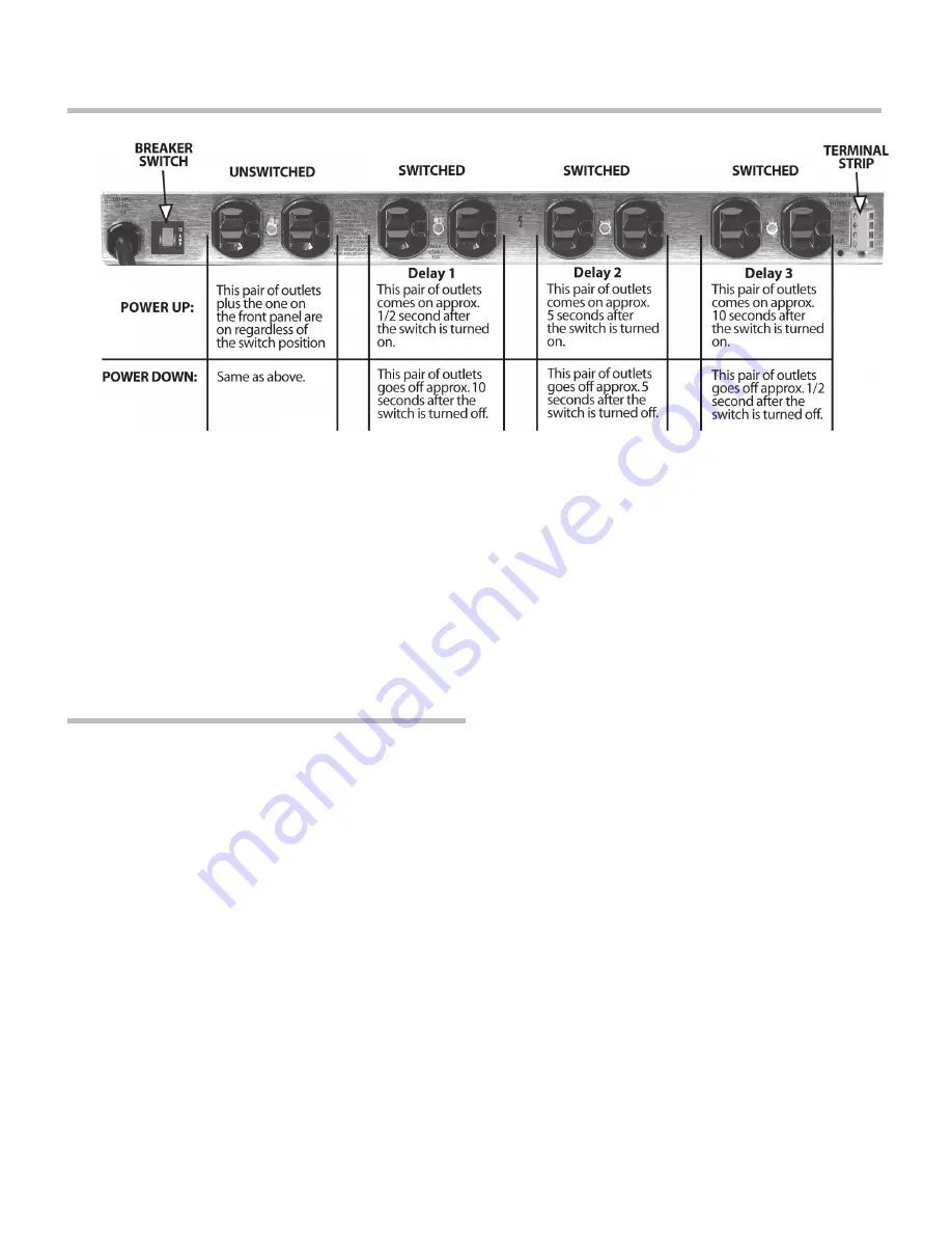
front panel screw that secure it. The delay adjust-
ment is Trimpot VR1, located on the printed circuit
board near the front left corner. It is the only trimpot
on the board. It is equipped with a thumbwheel
for easy adjustment. The range of adjustment
of the delay interval is from a minimum of about
1 second to a maximum of about 7 seconds.
reMote
switcHing
In the most basic configuration, only two wires
and an SPST switch are needed to initiate remote
ON or OFF sequence. The switch may be either a
momentary or maintained-contact type. If a third &
fourth wire are used, an LED may also be installed
at the remote end to indicate that the power is on.
Maintained vs. MoMentary
ContaCt switChing
Maintained switches, such as most toggle
switches and push-on/push-off switches (includ-
ing the Furman RS-1), stay open until switched
and then remain closed until switched again.
Momentary switches, usually pushbutton types
like the Furman RS-2, are normally open and
stay closed only as long as the button is pressed.
An on-off switch of either kind may be used
to actuate the PS-8R’s remote operation.
Maintained switches are generally most con-
venient when there is only one remote loca-
tion. When more than one switch location is
required, momentary switches allow the se-
quence to be started from different locations.
PS-8R main circuit board has 5 pairs of ter-
minals (PCB REV F and later) labeled as:
JMP1 (REM TO +12V = OFF), when the
REM and +12V terminals are tied to-
gether, the PS-8R will sequence OFF.
JMP2 (MOMENTARY), when the REM and
+12V terminals are momentary tied together,
the PS-8R will sequence ON or OFF.
JMP3 (REM TO +12V = ON), when the
REM and +12V terminals are tied to-
gether, the PS-8R will sequence ON.
JMP4 (REM TO GND = ON), when the
REM and GND terminals are tied to-
gether, the PS-8R will sequence ON (Note:
JMP1 must have a jumper installed).
JMP5, spare jumper holder.
The PS-8R unit comes factory-set for maintained
operation (jumper is installed on JMP1). It may be
easily converted to other operations by moving
jumper plug/plugs on the PS-8R’s circuit board.
to do this:
1. Disconnect the unit from AC power.
3


