
RVC-7W
- 12 -
Furman Sound, Inc.
1997 South McDowell Blvd.
Petaluma, California 94954-6919 USA
Phone: 707-763-1010
Fax: 707-763-1310
Web: www.furmansound.com
E-mail: info@furmansound.com
RVC-7W SPECIFICATIONS
Input:
120 VAC 7 Amps minimum capacity (hard wired) Out-
put: 120 VAC 7 Amps or 840 Watts maximum current
draw Outlets: 2 (Isolated Symmetrical Balanced A.C.
outlets) Protection: GFCI circuit protection for all AC
outlets
Transient Voltage
Surge Suppression:
Stand-off Voltage 200V Maximum Clamping Voltage
324V 10/1000 – 65,000 Watts @ 20uS. Test = 300,000
Watts Peak Power Handling
Noise Attenuation:
Transverse and Common Mode – Greater than 60dB.
1 MHz. – 1 GHz. Transformer: Breakdown voltage
1500V minimum Turns ratio 1:1 windings separated by
Faraday shield
Dimensions
Base Chassis:
14.5” H x 12” W x 3.28” D
Dimensions Front Panel: 17” H x 14” W x .078” D
Dimensions L-Brackets: 9.5”H x 3.75” W x 2.5” D
Dimension Depth
Overall (installed):
3.45” (from outside front panel) 3.375” from out side
wall surface
Weight:
42 lbs. (without brackets) Weight in shipping carton
(including brackets) 49 lbs.
Agency Listing:
C-ETL to U.L. standard #1012
INTRODUCTION
FEATURES
DESCRIPTION
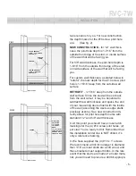
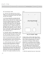
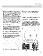
INSTALLATION
SAFETY
SPECS