

RVC-7W
- 4 -
that the
back
surface of the unit’s
back
back
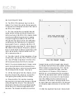
front
panel is
front
front
fl ush with the outside surface of the wall, and
the panel covers the wall cut-out. Because of
the Reference Series’ low-fl ux density trans-
former design, placement or proximity to a
Plasma or LCD screen is not critical, and the
RVC-7W does not produce any appreciable
heat.
INSTALLATION
1. Determine mounting location. The RVC-7W
is supported by two L-Brackets, which are fas-
tened to wall studs on either side of the RVC-
7W, so it’s necessary that the horizontal center
of the chosen mounting location be precisely
between two wall studs (+/- 3/8”).
2. We have supplied a cut-out template
(15.75” H x 13” W) that may be used for either
installation into a pre-existing wall space, or to
aid sheet-rock installers for new construction.
For installations where the RVC-7W is to be
located directly behind a Plasma Video Screen
wall mount bracket, pay attention to the verti-
cal spacing of the template/cutout. Ideally, the
Plasma screen should completely hide the
RVC-7W’s front panel. Additionally, the white
front panel will accept any household paint to
insure that it blends into the wall surface. To
further aid in your installation, make sure that
the RVC-7W’s signal wire and AC output cable
holes will clear your fl at Screen bracket (if one
is being used).
3. Whether your installation is a retrofi t or new
construction, it will be necessary to align and
mount the RVC-7W’s L-bracket pair. These
are supplied with each RVC-7W, and are also
supplied as a separate accessory (HRKIT-
RVCW).
4. Now it’s time to mark the position of the pilot
holes for the #10 screws. In a retrofi t, the chal-
lenge will be measuring, and putting the bracket
precisely in the right location. With new con-
struction it’s easier, however you MUST know
the exact depth of the wall material, (1/2” or 5/8”
is typical, but you must check).
Important - Steps 5 through 8 are critical for
proper installation of the RVC-7W!
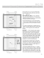
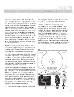
5. The right and left side brackets have
horizontal oval mounting cutouts, allowing
adjustment from back to front. Both have hole
centers in precisely the same place. For new
construction, marking the lines for the #10
screw pilot holes will be relatively simple. Once
you’ve determined where the vertical center of
your RVC-7W and or fl at screen will be, mark
the studs with a level to show your center line
(mark the long inside surface of the stud, not
the short side facing out). This can be done
with retrofi t installation as well, after the rect-
angular cutout has been made (a fl ash light or
stand mounted light may be necessary to see
clearly).
6. Mark a horizontal line 1/4” below the center
line, and 5-1/4” above (both studs). These are
the vertical pilot hole positions for the RVC-
7W’s L-bracket mounting holes. (See fi g. 1)
7. Now, cross these horizontal lines with the
vertical marks that will determine depth. For
new construction it will be critical to know the
depth or material thickness of the sheet rock,
plaster, or other wall surface material. Since
sheet rock is most common, and it’s usually
1/2” or 5/8”, we have done the math for these
INTRODUCTION
FEATURES
DESCRIPTION
INSTALLATION
SAFETY
SPECS


