background image

RVC-7W

- 6 -

ate to working with metal.
10. The RVC-7W’s brackets may now be in-

stalled. The “hooks” should be facing upwards 

to support the rectangular cutouts in the rear of 

the RVC-7W’s chassis.
11. For new construction remember that the 

signal and AC wiring will mount through the 

bottom surface of the RVC-7W’s chassis. Make 

sure there’s suffi cient signal wire or cabling 

to pass through the bottom of the RVC-7W, 

through the front panel cutout, and ultimately 

connecting to the fl at screen’s or projector’s 

input panel. The A.C. wiring for the RVC-7W 

typically requires less than 1ft. of wire beyond 

the bottom of the chassis. However, a service 

loop, or some slack is always a good idea, and 

there will be plenty of space below the RVC-

7W’s chassis to store it. 
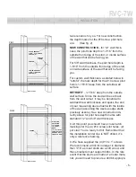
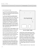
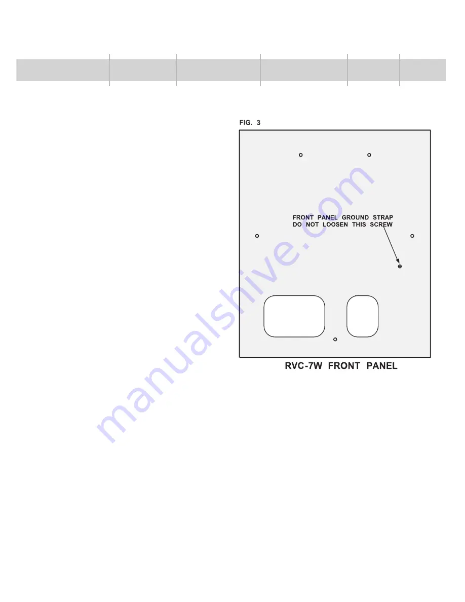
12. For either retrofi t, or fi nal installation of new 

construction, remove the RVC-7W from its car-

ton. Use a Phillips screwdriver to remove the 

(5) front panel screws from the front panel. 
NOTE: The screw located about 2” below center 

and to the right should not be loosened! It is a 

grounding strap screw, and is not used to attach 

the front panel to the chassis.  (See fi g. 3)
13. Lift the front panel from the chassis, (don’t 

lose the screws in the process). Loosen the 

front panel ground strap from the chassis.
14. Place the RVC-7W onto the mounting 

brackets (do not install cable clamps or thread 

wiring through the unit yet. The purpose for 

placing the chassis on the mounting brackets  

at this time is to check the alignment of the 

brackets. The chassis should rest on all four 

bracket hooks, and the forward edge should 

be virtually fl ush with the walls outside surface. 

If the chassis is recessed up to 1/32” (but no 

more), the front panel will simply “sink into” 

most sheet rock. However, if the chassis is 

sticking out, or is recessed too far, an adjust-

ment to the bracket position will be necessary. 

Both units have oval cutouts for depth adjust-

ment. Re-drilling into the studs will only be 

necessary if the vertical  measurements were 

so inaccurate as to make the RVC-7W hang at 

a noticeable angle clockwise or counter-clock-

wise.
15. After the alignment has been checked and 

INTRODUCTION

FEATURES

DESCRIPTION

INSTALLATION

SAFETY

SPECS

Summary of Contents for RVC-7W

Page 1: ...AC Power Conditioner 7 Amp In Wall Featuring Isolated Symmetrically Balanced Power and Narrow Bandwidth Technology O w n e r s M a n u a l IN T R O D U C T I ONS FEATURES DESCRIPTION INSTALLATION SAFE...

Page 2: ...in excess of 40dB at virtually all video frequencies up to 1 GHz Maintenance free transient voltage surge suppression protects your valuable equip ment while virtually eliminating costly service calls...

Page 3: ...LLATION PRELIMINARY Before unpacking your unit inspect the box and packing materials for any obvious dam age If internal damage is likely contact the carrier who delivered the unit before proceed ing...

Page 4: ...r These are supplied with each RVC 7W and are also supplied as a separate accessory HRKIT RVCW 4 Now it s time to mark the position of the pilot holes for the 10 screws In a retro t the chal lenge wil...

Page 5: ...h with the inside of the wall assuming the devices edge starts precisely at zero See new construction di rectly above for pilot hole depth marks with standard 1 2 and 5 8 wall thickness 8 At this poin...

Page 6: ...o the right should not be loosened It is a grounding strap screw and is not used to attach the front panel to the chassis See g 3 13 Lift the front panel from the chassis don t lose the screws in the...

Page 7: ...s for convenience and to neatly dress these wires and cables There is no connection to anything within the chassis 16 Once the conduit cable clamps are in place dress the signal wiring through the lar...

Page 8: ...studs This will off set any wobble or mechanical stress that might otherwise occur Use these only if necessary GROUND FAULT INTERRUPTER GFCI As the RVC 7W incorporates Isolated Sym metrically Balance...

Page 9: ...not be attempted with live AC wiring Input wiring must come from a switched electrical panel that has been disengaged Do not disassemble or modify in any way No user serviceable parts inside Keep away...

Page 10: ...Damaged equipment must remain available for inspec tion until the claim is nalized The Connected Equipment Warranty is also in effect for a period of three years unless the Purchaser does not complete...

Page 11: ...n of Furman with respect to the product If any part of this Limited Warranty is determined to be void or illegal the remainder shall remain in full force and effect Warranty claims should be accompani...

Page 12: ...Clamping Voltage 324V 10 1000 65 000 Watts 20uS Test 300 000 Watts Peak Power Handling Noise Attenuation Transverse and Common Mode Greater than 60dB 1 MHz 1 GHz Transformer Breakdown voltage 1500V mi...

Reviews: