

RVC-7W
- 7 -
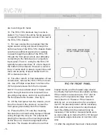
SYMM ETRICAL POWER ISOLATION TRANSFORMER
AC POWER CONDITIONER
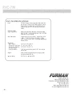
RVC-7W REFERENCE VIDEO CONDITIONER
INPUT: 120VAC 60HZ. 7AMP 1O
OUTPUT: 120VAC 1O ( 60VAC LINE / 60VAC NEUTRAL REFERENCED TO OUTPUT
GROUND) 60HZ. 7AMP MAX. GFI PROTECTED
CAUTION!
RISK OF ELECTRIC SHOCK. DO NOT REMOVE FRONT PANEL / COVER. REFER
SERVICING TO QUALIFIED SERVICE PERSONNEL. TO REDUCE RISK OF ELECTRICAL
SHOCK DO NOT EXPOSE THIS EQUIPMENT TO RAIN AND MOISTURE.
AVIS!
CIRCUIT COMMUN ISOLE DE LA MASSE A LA SORTIE. MEME SI LE COURANT A
LA SORTIE EST MUNI DE PROTECTION GFI, NE JAMAIS TOUCHER LES FILS
EXPOSES OU LES PARTIES EN METAL SANS TESTER POUR LA PRESENSE DE
TENSIONS A.C.!
ETL LISTED 3041249 CONFORMS TO ANSI /UL #1012
CERTIFIED TO CAN/ CSA E335-1/3E-94
L
N
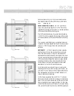
adjusted, remove the chassis and install the
cable clamps. We do not supply these, as they
are very common at any hardware or electrical
supply store, and individual installers will have
their preferences as to model and manufac-
ture. All we (and your local inspector) require is
that the cable clamps be standard CSA, C-UL,
C-ETL, or NRTL-C recognized cable clamps
(virtually all of them are at least one of these).
The larger hole on the bottom surface is for the
signal wiring and cables. It requires a 1” con-
duit cable clamp. The smaller hole to the right
is for the incoming AC wiring. It requires a 3/4”
conduit cable clamp.
NOTE: The hole, antechamber, and front panel
cutout for the signal wiring is for convenience and
to neatly dress these wires and cables. There is
no connection to anything within the chassis.
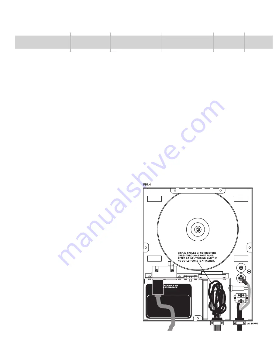
16. Once the conduit cable clamps are in place,
dress the signal wiring through the large clamp,
and the A.C. wiring through the small clamp.
Since the chassis is just over 40lbs. it may be
necessary to have a helper hold the unit during
this operation, or place it on a stand or table im-
mediately below the wall cut-out.
NOTE: It is absolutely imperative for safety that
the incoming AC wiring be DISENGAGED dur-
ing installation. The AC Power for the RVC-7W
MUST be supplied via a breaker panel that
uses a D.P.S.T. circuit breaker switched to the
OFF position. Spacing of the live contacts on
this switch must be at least 3 m.m. (virtually all
switched circuit breakers will meet this criteria).
DO NOT fail to check this prior to handling,
dressing, and installing these wires!
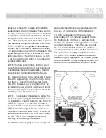
17. With the wires properly dressed through and
secured by the clamps, place the chassis on the
brackets for the remainder of the installation.
18. Trim the insulation off the wires (ap-
proximately 3/8” for Line and Neutral). Place
the Neutral wire into the A.C. terminal block
marked “N”, (bottom opening) and secure with
a slotted screwdriver. Place the Line wire into
the A.C. terminal block marked “L”, (bottom
opening) and secure with a slotted screwdriver.
The ground wire must be surely fastened to
the green 10-32 slotted screw on the bottom.
A listed ring lug, appropriate for the wire gauge
is recommended, though wrapping a solid core
wire around the screw is acceptable in some
INTRODUCTION
FEATURES
DESCRIPTION
INSTALLATION
SAFETY
SPECS


