


RVC-7W
- 9 -
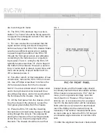
to your systems components. The GFCI is
located on top panel of the large rectangular
anti-chamber located on the RVC-7W’s lower
left corner. If the front panel is attached, and
you do not wish to remove it, the eraser side of
a pencil can easily reset the GFCI. When the
tab is properly reset, the blue AC output indi-
cator will light (assuming there is proper input
voltage to the unit).
SURGE PROTECTION
The RVC-7W is capable of suppressing virtu-
ally any instantaneous voltage surge. However,
the protection device may be damaged if the
over-voltage spike is sustained and extreme,
(such as a direct lightning hit). The device in
conjunction with the 7 Amp circuit breaker will
protect your valued equipment, but in extreme
circumstances, the protection device may
be damaged. If so, the circuit breaker/power
switch will not stay in the “on” position. If this
happens, your RVC-7W must be serviced,
though typically this will not be necessary.
SAFETY INFORMATION
Please read and observe all of the safety
and operating instructions before the
RVC-7W is operated.
● Installation should be limited to qualifi ed
service and installation professionals.
● Installation should not be attempted with
live AC wiring. Input wiring must come from
a switched electrical panel that has been
disengaged.
● Do not disassemble or modify in any way.
No user serviceable parts inside.
● Keep away from moisture and extreme
humidity.
● Do not allow liquids or foreign objects to
enter the unit.
● Standard lighting equipment may not be
connected to the RVC-7W, as household
light sockets are not designed for Balanced
Power. In accordance with the N.E.C.’s
standards for use of Balanced A.C. Power,
we recommend that the RVC-7W be limited
to use with video equipment, and screen art
accessories.
The RVC-7W should be serviced by qualifi ed
service personnel when:
● Objects have fallen on or liquid has spilled
into the unit.
● The unit has been exposed to rain or ex-
treme moisture.
● The unit will not operate, or function nor-
mally, showing a marked change in perfor-
mance.
● The unit has been dropped, or its enclosure
has been damaged.
● The power indicator will not light, even after
resetting the GFCI.
Note: The RVC-7W requires that a safety
ground be utilized from the source AC power
to the input of the Reference unit. This ground
connection is necessary for optimum perfor-
mance. Any attempt to operate the RVC-7W
without the incoming safety ground is consid-
ered improper operation and will invalidate the
warranty.
INTRODUCTION
FEATURES
DESCRIPTION
INSTALLATION
SAFETY
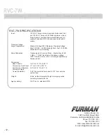
SPECS


