background image

13

Installation

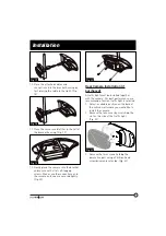
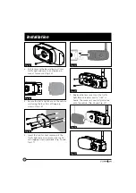
8. Repeat steps 1 to 7 to install the other 

camera. 

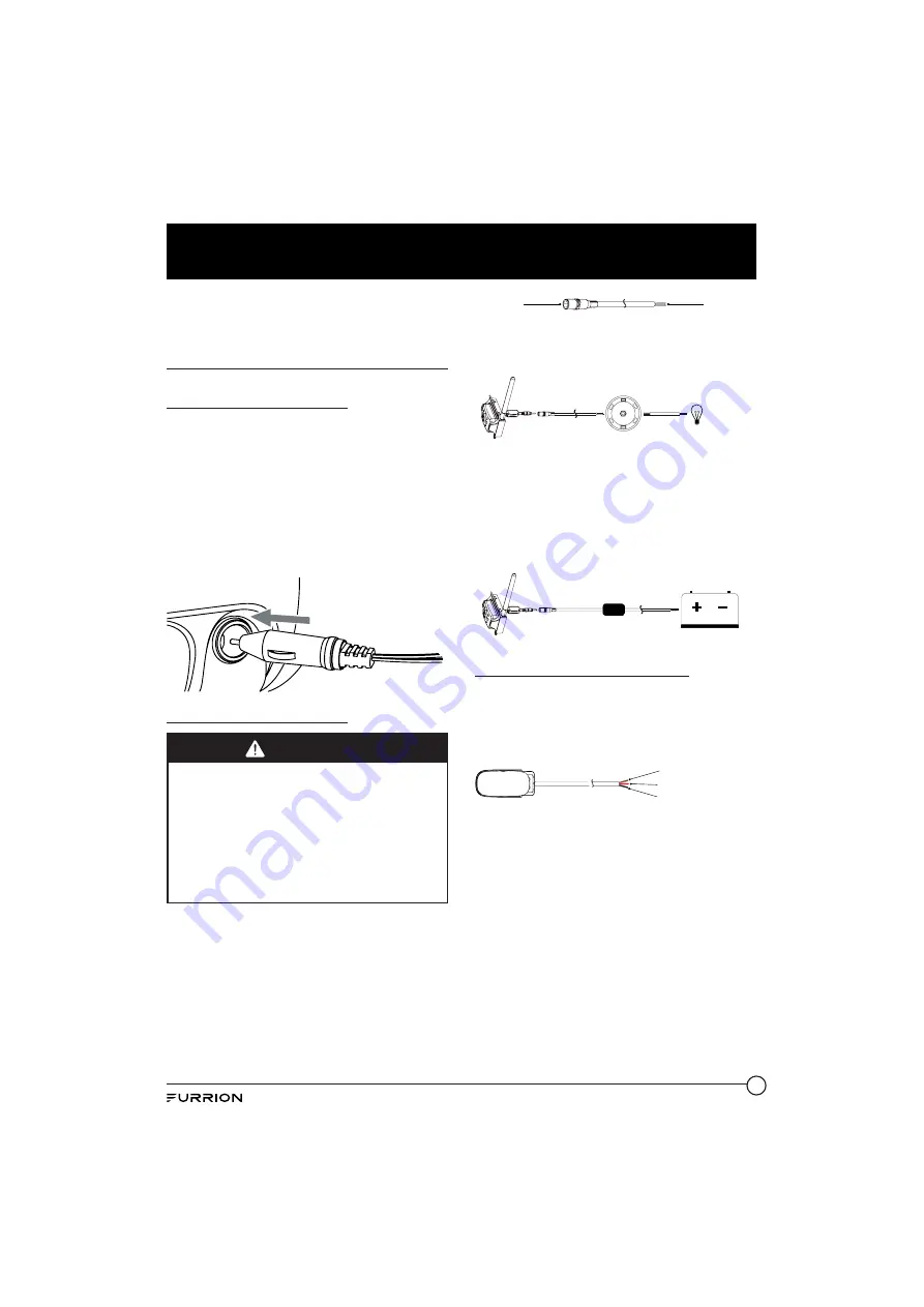
Electrical Connections

Connecting the Monitor

Ɣ

Route the power cable to the vehicle’s 
cigarette lighter socket 12/24V power 
outlet. The cable must not interfere with 
the safe operation of the vehicle.

Ɣ

Insert the small 12/24 Volt DC plug of 
the power cable into the right side of the 
monitor.

Ɣ

Plug the 12/24 Volt cigarette lighter plug 
into the vehicle’s cigarette lighter socket.

Connecting the Camera

WARNING

When connecting wires, ensure the circuit 
is isolated by disconnecting the negative 
terminal on the battery.

Ɣ

Ensure correct polarity when wiring the 
cables. RED + BLACK -.

Ɣ

Ensure correct polarity when wiring.

Ɣ

Wire connections and terminals must 
be sealed and waterproof.

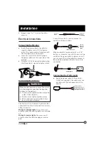
The Furrion Vision S Camera System can be 
connected to an electrical power source via a 
7 Way Connector.

Wiring to running lights:

 the camera will 

activate when the running lights are switched 
on.

Wiring to reverse lights: 

the camera will 

activate when the vehicle engages reverse 
gear.

Connects to
Camera

Connects to
12V/ 24V
Power Supply

Consult the vehicle’s service manual for 
specific wiring color code.

7 WAY CONNECTION

Running,
Reverse or 
Auxiliary
Lights

When wiring this camera directly to a 12V 
battery or converter in your RV, use an in-line 
switch on the power cable to power on or off 
your camera. This will enable this camera to 
be used when parked without a tow vehicle 
connected.

ON/OFF

DC POWER SUPPLY

IN-LINE SWITCH

Connecting the Traffi c Light

Ɣ

Route the power cable to the vehicle’s 
12/24V running light. The cable must not 
interfere with the safe operation of the 
vehicle.

Connects to Camera (red wire)

Grounding Wire (black wire)

Connects to Vehicle
Running Light (brown wire)

Tracffic light

Summary of Contents for FOS43TADS

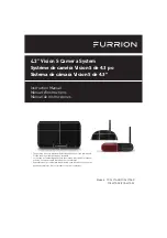
Page 1: ...ASR FOS43TASE FOS43TASF The packing contents may be different based on the kit you purchased Please take the actual product as standard Le contenu de l emballage peut tre diff rent en fonction de la t...

Page 2: ...maintenance of the product Please keep this instruction manual in a safe place for future reference This will ensure safe use and reduce the risk of injury Be sure to pass on this manual to new owner...

Page 3: ...stallation 8 What s in the Box 8 Monitor Installation 8 Camera Installation 8 Electrical Connections 13 Getting Started 14 Activate the Monitor 14 Pairing the Camera and Monitor 14 Change Settings 16...

Page 4: ...the procedures in this instruction manual Improper installation or modification of this product will void all warranties Many jurisdictions have laws and regulations relating to the use of cameras and...

Page 5: ...ntee is not responsible for any changes or modifications not expressly approved by the party responsible for compliance Such modifications could void the user s authority to operate the equipment NOTE...

Page 6: ...erference and 2 this device must accept any interference including interference that may cause undesired operation of the device RF Exposure The device has been evaluated to meet general RF exposure r...

Page 7: ...to add an additional safety tool for your vehicle CAUTION Do not back up your vehicle while watching the monitor screen Always look in the direction the vehicle is traveling Use the monitor as an aid...

Page 8: ...rom the ignition and isolate the 12V or 24V power source 1 Clean the mounting area where you are going to install the monitor with a cleaner that does not leave a residue 2 Remove the protective film...

Page 9: ...g the camera it is advisable to check if the intended mounting location will achieve adequate signal Pair the camera and monitor see Pairing the Camera and Monitor section Temporary secure the camera...

Page 10: ...pped or extruded Fig 13 Bracket Fig 13 5 Make sure the sealing lip around the edge of the gasket is seated over the edge of the bracket before fully tightening the screws 6 If only installing the moun...

Page 11: ...ctions and the camera antenna are secured tightly Fig 20 Fig 20 Rear Camera Installation if purchased A traffic light must be installed together with the camera For best performance we recommend a Fur...

Page 12: ...hicle wall using the four flat self tapping screws Fig 25 Fig 25 6 Insert the front or rear camera into the traffic light base and secure with two flat self tapping screws provided Fig 26 and Fig 27 F...

Page 13: ...ystem can be connected to an electrical power source via a 7 Way Connector Wiring to running lights the camera will activate when the running lights are switched on Wiring to reverse lights the camera...

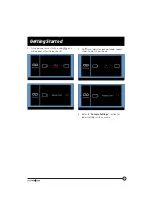
Page 14: ...g Activate the Monitor In off mode press the button on the right of the monitor to turn on the monitor In on mode press and hold the button to activate the monitor There are four options that allow yo...

Page 15: ...ted 2 Once paired successfully a red icon will appear after the device list 3 An icon indicates pairing failed repeat steps 2 and 3 to pair again 4 Refer to Camera Settings section for detail settings...

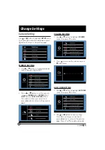
Page 16: ...ORMAL 0o ROTATE 90o FLIP 180o or FLIP ROTATE 270o Press to confirm your selection or press button to return to the previous page VOLUME SETTING 1 Use or button to highlight VOLUME menu then press to e...

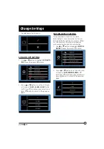
Page 17: ...rn to the previous page MOTION DETECT SETTING The motion detect function is used to detect objects in motion and assist in safe driving while the vehicle is in reverse When on the monitor LCD will be...

Page 18: ...highlight BRIGHTNESS CONTRAST or COLOR menu then press to enter 3 Press or to change the BRIGHTNESS CONTRAST or COLOR setting Press to confirm your selection or press button to return to the previous...

Page 19: ...video signal It is possible to receive signals from other cameras Systems such as security cameras baby monitors and even other back up camera systems can trigger the monitor to briefly turn on This i...

Page 20: ...e of the monitor with a soft cloth moistened with water or glass cleaner Only clean the unit with a dry cloth Do not clean the unit with strong chemical agents or abrasive cleaners Never spill liquid...

Page 21: ...TIME 250ms CAMERA IMAGE DISTANCE 5m CMOS SIZE 1 3 OPTICAL LENS F2 0 IR CUT FILTER 850nm automatic VIEW ANGLE 120 CURRENT IR ON 400mA 12V CURRENT IR OFF 200mA 12V CAMERA PIXEL 720x480 DISPLAY LCD POWER...

Page 22: ...Camera and Monitor Large dense objects could be obscuring the signal If possible move the objects Interference from electrical appliances may be affecting the wireless signal Turn off the appliances w...

Page 23: ...ce of product to any data software or information and normal wear and tear This warranty only protects the original end user you and is not transferable any attempt to transfer this warranty shall mak...

Page 24: ...TION OF INCIDENTAL OR CONSEQUENTIAL DAMAGES OR EXCLUSIONS OR LIMITATIONS ON THE DURATION OF IMPLIED WARRANTIES OR CONDITIONS SO THE ABOVE LIMITATIONS OR EXCLUSIONS MAY NOT APPLY TO YOU THIS WARRANTY G...

Page 25: ...toute s curit de l appareil Veuillez conserver le pr sent guide d utilisation en lieu s r pour vous y r f rer ult rieurement afin d assurer votre s curit et de r duire les risques de blessure Veuille...

Page 26: ...ent into an outlet on a circuit different from that to which the receiver is connected Consult the dealer or an experienced radio TV technician for help The device has been evaluated to meet general R...

Reviews: