background image

11

Operation

English

Many options will be installed prior to the 

purchase of your new RV, however there are a 

few options that you should be aware of while 

operating your new power center.
The built-in microprocessor selects the best 

mode for your battery automatically and 

determines which operating mode is best 

suited to recharge or maintain optimum 

battery condition. 

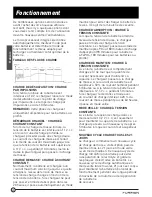
CHARGING FLOW CHART

 Time (Hrs)

Voltage (V)

DESULPHATION CHARGE - PULSE 

CHARGING

If the initial battery voltage is less than 10V, 

the charger will start desulphation mode with 

pulse charge profile. The pulse charge time 

will be 10 minutes.

NOTE: 

This charging phase is only available 

for Lead Acid Battery.

SOFT START - CONSTANT CURRENT 

CHARGING

If at the initial bulk charging, the battery 

voltage is less than 11Vdc due to deep 

discharge, the charger will go with soft 

charge. The bulk charging current is reduced 

to half of the maximum current until battery 

voltage is higher than 11Vdc or 10 minutes 

(whichever is longer) then switches to bulk 

charge.

BULK CHARGE - CONSTANT CURRENT 

CHARGING

Normally the battery is charged at constant 

maximum current until it rises to the bulk 

voltage level. The charging voltage changes 

with the battery voltage. If the charger cannot 

go to absorption mode within 20 hours, the 

charger will automatically go to float mode to 

prevent over charge of the battery. This is the 

safety timer. 

ABSORPTION CHARGE - CONSTANT 

VOLTAGE CHARGING

When the battery voltage rises to the bulk 

voltage level, the charging will switch to 

constant voltage charging. Charger will 

switch to float stage after 90 or 180 minutes 

of absorption charge (90 Minutes for LiFePO4 

battery, 180 Minutes for Lead Acid Battery).

FLOAT CHARGE - CONSTANT VOLTAGE 

CHARGING

In this stage, the battery is full and only 

takes in the amount of current necessary for 

maintaining the capacity. The charger will 

switch to bulk charge, if the battery current 

is higher than 50% of rated current for 5 

minutes or the battery voltage is lower than 

12.5Vdc for 5 minutes. If the charger remains 

at this mode with charging current less than 

20% of bulk current for over 60 hours, the 

charger will go into the standby mode.

STANDBY MODE - CONSTANT VOLTAGE 

CHARGING

In this stage, the charging voltage at this 

mode will be 13.2Vdc. This is only for 

maintaining the capacity. The charger will 

switch to a new cycle after 5 minutes when 

the current is higher than 6A. 

NEW CYCLE CHARGE EVERY 21 DAYS

Charger will start a new cycle charging of 

bulk to absorption to float every 21 days 

in either standby or float mode. This new 

cycle of charging will refresh the battery 

to prevent separation of the electrolyte & 

keep the electrode plates in good condition. 

The standby auto new cycle charge per 21 

days are designed to keep the battery in 

good working condition during long period 

of resting of the caravan or back up battery 

application.

Summary of Contents for Net-Zero FCVSWC42A

Page 1: ...All in One Power Center Centre d alimentation tout en un Centro de energ a todo en uno Instruction Manual Manuel d instructions Manual de instrucciones Model Mod le Modelo FCVSWC54A FCVSWC42A...

Page 2: ...nstallation and maintenance of the product Please keep this instruction manual in a safe place for future reference This will ensure safe use and reduce the risk of injury Be sure to pass on this manu...

Page 3: ...ional Features 6 Protective Features of the Power Center 6 Product Overview 7 Rear Panel 7 Front Panel 7 Installation 8 What s in the Box 8 Mounting the Power Center 8 Wiring Diagram 10 Wiring Connect...

Page 4: ...use CAUTION On a monthly basis check the fluid level in any battery connected to RV charging system follow battery maintenance procedures This product is not ignition protected and should not be insta...

Page 5: ...every 21 days a new charge cycle begins Protective Features of the Power Center BATTERY REVERSE POLARITY If a battery is accidentally hooked up backwards the power center converter will be protected...

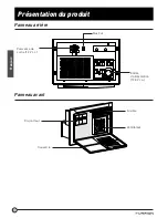
Page 6: ...7 Product Overview English Rear Panel Fur Bus Power Input 120Vac Power Output 12Vdc Front Panel Breaker Cover Fan Fuse...

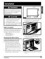
Page 7: ...Instruction Manual x 1 Warranty Card x 1 Mounting the Power Center Consult a licensed electrician or an RV technician for installation assistance 1 Select a mounting location near the shore power and...

Page 8: ...to connect the wires 7 Slide the power center into the opening area and affix with 4 self tapping screws 8 18 thread not supplied Fig 5 and Fig 6 Fig 5 Fig 6 8 Replace the housing to the power center...

Page 9: ...unit Replace only with same type and rating NOTE If the reverse battery protection fuses are blown during connection be sure that the battery has been connected properly then replace the fuses with t...

Page 10: ...er charge of the battery This is the safety timer ABSORPTION CHARGE CONSTANT VOLTAGE CHARGING When the battery voltage rises to the bulk voltage level the charging will switch to constant voltage char...

Page 11: ...ve the converter output wires from the DC board ground and positive 3 Finally unscrew the screws that hold the metal converter plate to the plastic housing For factory repairs return only the converte...

Page 12: ...cy at LiFePO4 120Vac 80 80 Line Regulation At Full Load input voltage105V to 132V 3 3 Load Regulation 10 100 Load 3 3 Certification UL458 UL67 FCC PART 15b UL458 UL67 FCC PART 15b Working Environment...

Page 13: ...nverter Improve ventilation to the compartment Excessive load for converter Reduce load requirements or install larger converter Input voltage too low Correct input supply voltage Bad battery cell s R...

Page 14: ...urface of product to any data software or information and normal wear and tear This warranty only protects the original end user you and is not transferable any attempt to transfer this warranty shall...

Page 15: ...MITATION OF INCIDENTAL OR CONSEQUENTIAL DAMAGES OR EXCLUSIONS OR LIMITATIONS ON THE DURATION OF IMPLIED WARRANTIES OR CONDITIONS SO THE ABOVE LIMITATIONS OR EXCLUSIONS MAY NOT APPLY TO YOU THIS WARRAN...

Page 16: ...et l entretien en toute s curit de l appareil Veuillez conserver le pr sent guide d utilisation en lieu s r pour vous y r f rer ult rieurement afin d assurer votre s curit et de r duire les risques de...

Page 17: ...elles 20 Caract ristiques de protection du centre d alimentation 20 Pr sentation du produit 21 Panneau arri re 21 Panneau avant 21 Installation 22 Contenu de la bo te 22 Montage du centre d alimentati...

Page 18: ...le fusible uniquement par un fusible du m me type et du m me calibre MISE EN GARDE Tous les mois v rifiez le niveau de liquide dans toute batterie connect e au syst me de charge du VR et suivez les pr...

Page 19: ...nce Caract ristiques de protection du centre d alimentation POLARIT INVERSE DE LA BATTERIE Si une batterie est accidentellement branch e de fa on inverse le convertisseur du centre d alimentation sera...

Page 20: ...21 Pr sentation du produit Fran ais Panneau arri re Bus Fur Entr e d alimentation 120 V c a Puissance de sortie 12 V c c Panneau avant Disjoncteur Couvercle Ventilateur Fusible...

Page 21: ...actez votre d taillant Centre d alimentation x 1 Manuel d instructions x 1 Carte de garantie x 1 Montage du centre d alimentation Consultez un lectricien agr ou un technicien de VR pour obtenir de l a...

Page 22: ...ur savoir comment connecter les fils 7 Faites glisser le centre d alimentation dans la zone d ouverture et fixez le avec 4 vis autotaraudeuses filetage no 8 18 non fournies Fig 5 et Fig 6 Fig 5 Fig 6...

Page 23: ...fusibles du m me type et du m me calibre REMARQUE Si les fusibles de protection de batterie invers e grillent pendant le raccordement assurez vous que la batterie a t correctement connect e puis remp...

Page 24: ...ures il passe automatiquement en mode maintien pour viter de charger la batterie l exc s Il s agit de la minuterie de s curit CHARGE D ABSORPTION CHARGE TENSION CONSTANTE Lorsque la tension de la batt...

Page 25: ...ez les fils de sortie du convertisseur depuis le circuit int gr CC la mise la masse et le positif 3 Enfin d vissez les vis qui maintiennent la plaque m tallique du convertisseur sur le bo tier en plas...

Page 26: ...t LiFePO4 120 V c a 80 80 R gulation de ligne pleine charge tension d entr e 105 V 132 V 3 3 R gulation de charge 10 100 de charge 3 3 Norme UL458 UL67 FCC PART 15b UL458 UL67 FCC PART 15b Environneme...

Page 27: ...tilation du compartiment Charge excessive pour le convertisseur R duisez les besoins de charge ou installez un convertisseur plus puissant Tension d entr e trop faible Corriger la tension d alimentati...

Page 28: ...DONN ES LOGICIELS OU RENSEIGNEMENTS AINSI QUE L USURE NORMALE LA PR SENTE GARANTIE PROT GE UNIQUEMENT L UTILISATEUR FINAL INITIAL VOUS ET NE PEUT TRE C D E QUICONQUE TOUTE TENTATIVE DE CESSION DE LA P...

Page 29: ...TATIONS DES PR JUDICES ACCESSOIRES OU CONS CUTIFS NI LES EXCLUSIONS OU LIMITATIONS DE LA DUR E DES GARANTIES OU CONDITIONS IMPLICITES POUR CE MOTIF LES LIMITES ET EXCLUSIONS PR C DEMMENT NONC ES POURR...

Page 30: ...ucciones contiene la informaci n para la instalaci n el mantenimiento del producto y el uso sin riesgos Mantenga este manual de instrucciones en un lugar segura para que le sirva de referencia futura...

Page 31: ...cter sticas protectoras del Centro de energ a 34 Descripci n del producto 35 Panel trasero 35 Panel frontal 35 Instalaci n 36 Contenidos de la caja 36 Montaje del Centro de energ a 36 Instalaci n 37 D...

Page 32: ...lo con un fusible del mismo tipo y de la misma clasificaci n PRECAUCI N Cada mes verifique el nivel de l quido de las bater as conectadas al sistema de carga de RV y siga los procedimientos de manteni...

Page 33: ...carga Caracter sticas protectoras del Centro de energ a BATER A DE POLARIDAD INVERSA si una bater a se conecta accidentalmente al rev s el convertidor del Centro de energ a estar protegido por el fusi...

Page 34: ...35 Descripci n del producto Espa ol Panel trasero Fur Bus Entrada de energ a 120 VCA Potencia de salida 12 VCC Panel frontal Interruptor autom tico Cubierta Ventilador Fusible...

Page 35: ...dor Centro de energ a x 1 Manual de instrucciones x 1 Tarjeta de garant a x 1 Montaje del Centro de energ a Consulte a un electricista con licencia o un t cnico de RV para asistencia en la instalaci n...

Page 36: ...de cableado para saber c mo conectar los cables 7 Deslice el Centro de energ a en el rea de apertura y f jelo con 4 tornillos autorroscantes rosca n 8 18 no incluidos Fig 5 y Fig 6 Fig 5 Fig 6 8 Vuelv...

Page 37: ...el mismo tipo y calificaci n NOTA Si los fusibles de protecci n inversa de la bater a se queman durante la conexi n aseg rese de que la bater a se haya conectado correctamente luego reemplace los fus...

Page 38: ...carga de la bater a Este es el temporizador de seguridad CARGA DE ABSORCI N CARGA DE VOLTAJE CONSTANTE Cuando el voltaje de la bater a aumente al nivel de voltaje masivo la carga cambiar a una carga d...

Page 39: ...lida del convertidor de la placa de CC a tierra y positivo 3 Finalmente desatornille los tornillos que sujetan la placa del convertidor de metal a la carcasa de pl stico Para reparaciones en f brica d...

Page 40: ...en LiFePO4 120 VCA 80 80 Regulaci n de l nea completa Carga a voltaje de entra da de 105 V a 132 V 3 3 Regulaci n de carga 10 a 100 de carga 3 3 Est ndar UL458 UL67 FCC PART 15b UL458 UL67 FCC PART 15...

Page 41: ...de aire al convertidor Mejore la ventilaci n del compartimiento Carga excesiva para el convertidor Reducir Celdas de bater a defectuosas El voltaje de entrada es demasiado bajo Corrija el voltaje de s...

Page 42: ...PRODUCTO A CUALQUIER TIPO DE DATOS SOFTWARE O INFORMACI N Y EL DESGATE NORMAL ESTA GARANT A SOLO PROTEGE AL USUARIO FINAL ORIGINAL USTED Y NO ES TRANSFERIBLE CUALQUIER INTENTO DE TRANSFERENCIA RESULT...

Page 43: ...SABILIDAD POR DA OS INCIDENTALES O DERIVADOS O EXCLUSIONES O LIMITACIONES SOBRE LA DURACI N DE LAS GARANT AS IMPL CITAS O CONDICIONES EN CUYO CASO LAS LIMITACIONES O EXCLUSIONES ANTERIORES PODR AN NO...

Page 44: ...8 354 5792 Email support furrion com 2007 2018 Furrion Ltd Furrion and the Furrion logo are trademarks licensed for use by Furrion Ltd and registered in the U S and other countries 2007 2018 Furrion L...

Reviews: